Technical Request for Cruise Control Wiring installation diagram

Currently reading:
Technical Request for Cruise Control Wiring installation diagram

Raaj

New member
Joined
Oct 21, 2015
Messages
15
Points
2
Hi friends,

This is Raaj from India. I request some helps regarding cruise control installation.

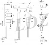
I own an Abarth in India which is based on Tjet engine and Punto. It doesn't have Cruise Control. So, I imported combination switch that has lights, wipers and cruise controls on it. Its part number is 735521318

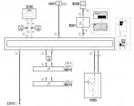
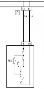
Now, I want some help regarding the installation of this stalk switch. If possible, can you get me Abarth 1.4 Tjet cruise control wiring map? Especially the Can/Body control wiring for Cruise Control.

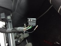
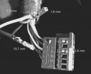
The stalk switch I got is this...
Combs.jpg


Please help me and thanks in advance

Regards,
Raaj
 
Hi Raaj, ky a al kal eh ? (sorry for the phonic writing ;-)

The connection should be straigth forward as the harness normally has the necessary wires connected to both sides (stalk and body computer). You will also have to activate the cruise option with MES once the new stalk is installed.

Before doing anything, can you do me a favor please ?? I need to know how the switches are arranged Inside the stalk; I know FIAT uses a combination of resistors to tell the ECU what the driver wants, this resulting resistance can be red from the connector on the stalk between pins 8 and 10. Please hook a DVM to the stalk and give the resistor for the various positions:
- OFF
- ON
- UP(+)
- DOWN (-)
- RESUME

Thanks a lot in advance, here's the switch drawing …

BRs, Bernie

If someone here helped You fix -or better, understand- your issue, hit the thanks icon @ bottom right corner, it's free and makes us feel helpy ;-)
 

Attachments

  • CruiseControl switch.JPG
    CruiseControl switch.JPG
    14.4 KB · Views: 334
Hi Raaj, ky a al kal eh ? (sorry for the phonic writing ;-)


Hi Bernie. Thanks for the kind reply and appreciate your help. Didn't understand Ky a al kal eh though. :)

The connection should be straigth forward as the harness normally has the necessary wires connected to both sides (stalk and body computer). You will also have to activate the cruise option with MES once the new stalk is installed.


Thanks for the diagram. I thought it works for Punto Multijet versions only. Nice to know it's the same installation for Abarths too. Sadly, my car doesn't have harness for Cruise Control, hence its troublesome. Moreover, I don't know how to access the body computer for the right port i.e. port number 41. If someone could help me on that, that would be fantastic.

Before doing anything, can you do me a favor please ?? I need to know how the switches are arranged Inside the stalk; I know FIAT uses a combination of resistors to tell the ECU what the driver wants, this resulting resistance can be red from the connector on the stalk between pins 8 and 10. Please hook a DVM to the stalk and give the resistor for the various positions: - OFF - ON - UP(+) - DOWN (-) - RESUME

I already tested my ECU with port number 85 by sending required power to it. I found it can be done by accessing the port numbers 84,85,86 and 61 like some folks did with Alfa147 stalk. But, I wanted to do it via BCM with OEM combination switch. BTW, what is a DVM? can you say little more on that please?


BTW, I opened the shrouds of my Steering to see the harness of my car. I found there is no wiring for Cruise Control i.e. from 8 pin in combination switch to 41 port in Body computer. So, I may need to do it manually. Please help me how to locate the number 41 port in body computer.

Harness in my Abarth
Stock Combi wiring.jpg

You can see blank ports in the harness connector. Number 6, 8, 11 and 12. Out of that, number 8 is Cruise Control Port
CombiConnectorblankports.jpg


Now the million dollar question is, how to find port number 41 in body computer? Does my body computer have it at all?


Some details about my car ECU and Body computer:

ECU: Bosch ME7.9.10
Bosch Number: 0261S11343
Fiat Number: 55269849
Software Number: 555777

Body Computer Details:
Fiat drawing number: 51966727
Hardware Number: BC323L.0100
Hardware Version: 03
Software Number: 04440004106
Software Version: F002


Thanks and looking forward for the further help.
 
Hi Raaj,

was supposed to mean "how are you doing ?" in Urdu, but most probably forgot exactly how to say/write it ;-)

Anyway, here are some more info about the petrol engine cruise control. You'l have to run an extra wire from stalk connector pin 8 to BCM D connector pin 41. But it is not sure the BCM has provision to process that signal for sending to ECU via the CAN bus…

I'm pretty sure mine has (since the wire is already there) so I really need you to measure the RESISTANCE between pin 10 and 8 ON THE STALK for the 5 possible positions. As there is a diode in the stalk, you'll have to connect the Digital Volt Meter (DVM) in the right way (positive on pin 8) or you won't read anything.
Obviously with the switch OFF, the circuit should show infinite resistance(open circuit), with switch turned ON, should read 2480 ohms (ish) and other values when the different switches are toggled…

BRs, Bernie

If someone here helped You fix -or better, understand- your issue, hit the thanks icon @ bottom right corner, it's free and makes us feel helpy ;-)
 

Attachments

  • Cruise Control Petrol.JPG
    Cruise Control Petrol.JPG
    67 KB · Views: 436
  • Body Computer Module connector D.JPG
    Body Computer Module connector D.JPG
    17 KB · Views: 329
  • stalk commands.doc
    22.5 KB · Views: 128
Hi Raaj, was supposed to mean "how are you doing ?" in Urdu, but most probably forgot exactly how to say/write it ;-)

Oh Okay, I thought it was some kind of Hello in your local language. Iam fine Bernie, thank you. Hope you are doing fine as well.

You'l have to run an extra wire from stalk connector pin 8 to BCM D connector pin 41. But it is not sure the BCM has provision to process that signal for sending to ECU via the CAN bus…

Yes, its still a mystery whether my Car's Body computer has provision for pin number 41 and have such process. Can you please tell me how to identiy this Pin 41 in my body computer?


I'm pretty sure mine has (since the wire is already there)


Good to know. May I know which car and variant it is and what type of engine? Also, the pictures you are sharing, are from Abarth eLearn or from Grande Punto eLearn? If its Abarth eLearn or if you have Punto Abarth workshop manual, kindly share a copy with me.


I really need you to measure the RESISTANCE between pin 10 and 8 ON THE STALK for the 5 possible positions. As there is a diode in the stalk, you'll have to connect the Digital Volt Meter (DVM) in the right way (positive on pin 8) or you won't read anything. Obviously with the switch OFF, the circuit should show infinite resistance(open circuit), with switch turned ON, should read 2480 ohms (ish) and other values when the different switches are toggled…


I was confused with DVM. We usually call it as Digital Multi-meter. And yes, I already tested resistance from stalks. It works exactly like you described. :)


BTW, thanks for sharing Stalk commands. May I know why port numbers 6, 11 and 12 are not connected? What are they for? Can we make them work for any other things?


And the bottom line is, How to identify the Port number 41 in Body computer? I was told it usually will be on the backside of Body Computer. Have they changed it to front side due to convenience to access it? Should I completely dismantle the fusebox to access the Body computer?

Looking forward for the further guidelines on the things I have mentioned. Thanks a lot.
 
Last edited:
Hi Raaj,

the D connector is located at the back of the body computer and you're right, you'll have to remove it from the car to access it.

- remove ALL front connectors: have to lift the plastic handle while gently pulling the housing
- unscrew (3) BCM bolts ("E" type sockets)
- you'll then have access to the 2 back connectors with similar plastic handle locks
- once ALL connectors removed you can get the BCM out the car
- open it, you'll need four or six hands and as much screwdrivers/plyers etc.
- from there you can hopefully tell (if circuit is not sealed) is there is a provision for cruise control

You can see the pinout in the attachments I sent.

Have you made a table of the resistance you measured in the various status of the stalk ? Could you measure them in both way or is the schematic with the diode correct. Sorry to insist on this but I NEED to know the ACTUAL values !

BRs, Bernie

If someone here helped You fix -or better, understand- your issue, hit the thanks icon @ bottom right corner, it's free and makes us feel helpy ;-)
 
Hi Raaj, the D connector is located at the back of the body computer and you're right, you'll have to remove it from the car to access it.
- remove ALL front connectors: have to lift the plastic handle while gently pulling the housing
- unscrew (3) BCM bolts ("E" type sockets)
- you'll then have access to the 2 back connectors with similar plastic handle locks
- once ALL connectors removed you can get the BCM out the car
- open it, you'll need four or six hands and as much screwdrivers/plyers etc.
- from there you can hopefully tell (if circuit is not sealed) is there is a provision for cruise control. You can see the pinout in the attachments I sent.


Bernie, thanks a lot for your awesome co-operation and step by step guidance. I shall work on it this weekend and will update on that.

Sorry for asking too many questions, but I need to confirm them for trouble free experience while opening BCM. So, here a couple of....

- What kind of Pin I may need to wire on BCM connector, if I found Pin number 41 on the backside of BCM connector? Why am asking it is, If i get it wired, I don't need to open it again at the time of new Stalk installation.


- And what measures should I take to make it trouble free while taking the wire from 41 pin.

Have you made a table of the resistance you measured in the various status of the stalk ? Could you measure them in both way or is the schematic with the diode correct. Sorry to insist on this but I NEED to know the ACTUAL values !


Sorry Bernie. No, I didn't recorded any values or made any table for that. I just made sure there were values with each operation from 8 to 10 pin numbers while moving to different steps i.e. On/Off, Res, Up+ and Down -.
 
- What kind of Pin I may need to wire on BCM connector, if I found Pin number 41 on the backside of BCM connector?

- And what measures should I take to make it trouble free while taking the wire from 41 pin.

Sorry Bernie. No, I didn't recorded any values ...

- the D connector has the same pins as the stalk, if I remember well...
- the 41 position should be empty in the plug so just add the pin & wire and route it to the stalk connector...
- bad news you haven't recorded anything.

I NEED the EXACT behaviour of the resistors/diode combination in order to mimic the stalk with a couple of switches/push buttons (poor man stalk) and I'd really appreciate if you could build that table because the switch drawing in eLearn makes no sense with the eLearn test procedure ...
From the drawing, when in ON, there is NO PATH for anything to go from 8 to 10, but they pretend we should read 2480(ish) ohms ...


BRs, Bernie

If someone here helped You fix -or better, understand- your issue, hit the thanks icon @ bottom right corner, it's free and makes us feel helpy ;-)
 

Attachments

  • Stalk pins 8 and 10.JPG
    Stalk pins 8 and 10.JPG
    68.2 KB · Views: 241
  • CruiseControl switch.JPG
    CruiseControl switch.JPG
    14.4 KB · Views: 288
- the D connector has the same pins as the stalk, if I remember well...
- the 41 position should be empty in the plug so just add the pin & wire and route it to the stalk connector...


D connector.jpg
This is how D connector looks like. This is from old generation Body computer which has less numbered pins. Hopefully, I wish my car could have 60 pins. :)


I NEED the EXACT behaviour of the resistors/diode combination in order to mimic the stalk with a couple of switches/push buttons (poor man stalk) and I'd really appreciate if you could build that table because the switch drawing in eLearn makes no sense with the eLearn test procedure ...From the drawing, when in ON, there is NO PATH for anything to go from 8 to 10, but they pretend we should read 2480(ish) ohms

From my understanding, from stalk Pin number 8, all CC signals reach to Pin number 41 where it decodes and send the requested signal to ECU. So, IMHO, essentially BCM should acts as a decoder as for CC stalk signals is concerned.


I will try to record the signals tonight using Multimeter and build a table and share it here.

Thanks & Regards,
Raaj
 
Hi Raaj,

sorry your car doesn't have the same connector a in eLearn :-( How old is it ?

Regarding the signal & pin 8, it's the central point of a bridge divider where one leg is in the stalk an the other in the BCM. The resulting voltage is converted in the BCM and then sent to the ECU thru CAN line … What I'm interested in is the behaviouor of the stalk side leg of this bridge .

Thanks, Bernie
 
sorry your car doesn't have the same connector a in eLearn :-( How old is it ?

I didn't understand what you meant. What connector you are talking about?

My car was made in September 2016, bought in April 2017. The variant I got is, Urban Cross Abarth.

Abarth was released in three variants in India based on Punto Platform like below
1. Punto Abarth
2. Avventura Abarth (Crossover with hatchwheel)
3. Urban Cross Abarth (Crossover without hatchwheel)

Regarding the signal & pin 8, it's the central point of a bridge divider where one leg is in the stalk an the other in the BCM. The resulting voltage is converted in the BCM and then sent to the ECU thru CAN line … What I'm interested in is the behaviouor of the stalk side leg of this bridge .

I shall try my best to make the table with signals between 8 and 10. Thanks.
 
Resistance mode observations during my checks with Digital Multimeter from pin 8 to 10 in NEW stalk switch. All values are in Ohms.

OFF 1
ON (It shows diverse figures ranging from 10.94 to 17 plus. It just blinks one value and then return to 1)
UP (+ ) 3.41
DOWN (-) - 7.34
RESUME 128
 
Hi Raaj,

thanks a lot for your efforts ! The table you build kind off correspond to what's given in eLearn test procedure:

ON: 2480 Ω
Set+: 345 Ω
Set-: 740 Ω
Res : 132 Ω

So beside the decimal point and the ON value, that seem to match. Was you DMM set to Auto range ?

Regarding the connector I was refering to the pinout I sent with post #4 . As your Abarth is 2016 the BCM is probably a newer version of the one in ePear and therefore I'm not even sure the stalk pin 8 connects to pin 41 @ BCM :-(

That's why I wanted to build a poor-man's stalk to activate the cruise control on my GP before spending money to get a useless trophy on my shelf ...

Good luck though, kind regards, Bernie
 
thanks a lot for your efforts ! The table you build kind off correspond to what's given in eLearn test procedure:
ON: 2480 Ω
Set+: 345 Ω
Set-: 740 Ω
Res : 132 Ω
So beside the decimal point and the ON value, that seem to match. Was you DMM set to Auto range ?

You are welcome Bernie. Iam sure our discussions will be very helpful to the community. So, glad to share that thing here.


I couldn't see the testing procedure in Eleran. Can you direct me where I should see that in Elearn?


Please see the following picture for my settings for the test.
Multi meter.jpg

Good luck though, kind regards, Bernie

Thank You Bernie. Hopefully, they have 60Pin BCM in my car. I will try to access that this weekend and see what's there in my car.

BTW, is there any procedure we can check the stalk switch without installing it in the car. I mean with proper wiring connections from car, but without physical installation. Hope you got my point.

Thanks & Regards,
Raaj
 
Last edited:
Hi Raaj,

I thought you were showing the picture of YOUR bcm, now I understand it's an old one… Correct ?

I'm afraid the loom will be too short to connect the stalk without it being in place, so you can't test the cruise control feasability without phisically installing the stalk, unless you can mimic the stalk as I am trying to do …

Regarding your setup, the ON position being >2000 Ω it is normal that your display shows diverses values and then switch to 1. You should select the next higher value (20K), you would then read 2.48 for 2480Ω and 0.74, 0.34, 0.13 for the other positions. If you can confirm this I will provide a drawing with 2 switches, 2 pushbuttons and 4 résistors + 1 diode that you can use to build the poor man's stalk…

BRs, Bernie
 
I thought you were showing the picture of YOUR bcm, now I understand it's an old one… Correct ?

Oh yes, that was an old BCM of Punto of Pre 2014 models. I still haven't opened my own BCM. I shall open it on weekend and end the suspense. :)


I'm afraid the loom will be too short to connect the stalk without it being in place, so you can't test the cruise control feasability without phisically installing the stalk, unless you can mimic the stalk as I am trying to do …


I assume, loom can reach upto upper 12 pin connector of new stalk without installing it. If that's the case, I think we can ignore the other 12 connector and unplug it from original stalk which is meant for Airbag, Radio and horn modules. If that's Ok, I will try to connect just the upper side of connector and check how it behaves with car wiring.


If you can confirm this I will provide a drawing with 2 switches, 2 pushbuttons and 4 résistors + 1 diode that you can use to build the poor man's stalk…

I know this method. My friend Mr. Rajan has installed it in his Linea Tjet a very long ago. This method is possible in my Abarth as well, as I already tested that method in my Abarth by powering ECU port number 85. But iam very much interested in stock setup like you have in Europe Punto models. Unless the original stalk method is not suitable, iam not interested on the other method. Thank You.
 
Hi Raaj,

if you want to get Something about Cruise Control, search for code 5580A and E5060 in eLearn …

BRs, Bernie
 
Last edited:
Hi Raaj,

in reply to your PM, the pins are supposed to be Dupont style 0.1" and you should find them easily in India as in all parts of the world since they are used almost everywhere (together with Molex)

BRs, Bernie
 

Attachments

  • Crimp pin Dupont 0.1 female.JPG
    Crimp pin Dupont 0.1 female.JPG
    40.6 KB · Views: 129
  • Crimp pin Dupont 0.1 male.JPG
    Crimp pin Dupont 0.1 male.JPG
    35.7 KB · Views: 136
Have done some "on picture" measurement. Not high precision but you get the idea…

1.4mm is the reference for the wire I've used to build the derivation.
1.6mm is the squared end side
10.7mm is the length (possibly perspective distorded)
12.6mm is for 5 holes, should be 12.7 for a standard 0.1" pitch

BRs, Bernie

If someone here helped You fix -or better, understand- your issue, hit the thanks icon @ bottom right corner, it's free and makes us feel helpy ;-)
 

Attachments

  • Crimp dupont LR.jpg
    Crimp dupont LR.jpg
    1.1 MB · Views: 184
Last edited:
Back
Top