General Dell'Orto 32/28 FZD

Currently reading:
General Dell'Orto 32/28 FZD

Joined
Aug 3, 2009
Messages
1,501
Points
365
Location
Sunshine Coast, Australia
A few years ago during the restoration of my 500F, I decided to build myself a 695cc engine and in doing so, replaced the Weber IMB carburettor with a Dell'Orto 32/28 FZD.
As far as I know, these carburettors were never standard equipment on any cars. They were manufactured as an after market item and used by tuners in the 60s and 70s on small 2 to 4 cylinder engines.

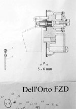
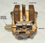
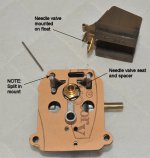
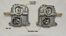
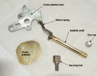
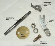
The FZD is a single throat design with a main butterfly and a inline secondary butterfly in the starting (choke) circuit.
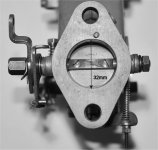
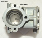
It is a 'tilted sidedraft' carburettor with the main throat sitting 20 degrees up from horizontal.
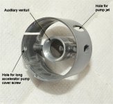
The main throat is either 30mm or 32mm in diameter fitted with a 24mm or 28mm removable auxilliary venturi respectively.
There may be other variations, but the 30/24 and 32/28 are the main ones.
Manifolds for the Fiat 500/126 engines are still commonly available.

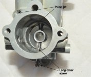
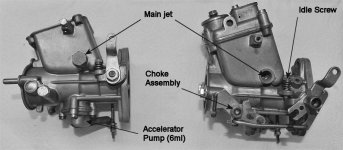
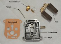
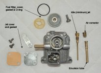
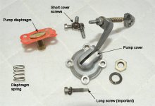
The main advantages over the IMB are the presence of an accelerator pump, a larger dual chamber fuel bowl which is much less prone to foaming, better thermal isolation with maybe easier hot starting and a larger variety of tuning components.
Disadvantages are relative rarity, price and availability of some components though this seems to be improving with at least two web sites offering a nice range of parts (www.dellortoshop.com/ and www.dellorto.co.uk/).
Rebuild kits are also available.

When I bought my FZD, I got a two for one deal though the second carby was missing several parts and had many stripped threads. In my excited haste to get my engine going I replaced a few gaskets, bolted on the good carby and started driving. I promised myself that I'd clean and service it one day. Well a couple of weeks ago that day came.
For no compelling reason other than a bit of spare time, I removed it, stripped it and rebuilt it. Along the way I took lots of photos which I'll attach to the next few posts.
I've also scanned what little information I have including my rough translation of the Italian text and attached the pdf to this post.

So here goes ...
Chris
 

Attachments

  • FZD Schematic Diagram.pdf
    538 KB · Views: 360
Last edited:
FZD Variants

In the following and for the sake of clarity, I'll refer to the face on the carby with the logo as the front and the opposite side as the rear. LHS/RHS is the usual convention - ie: as you look from the rear toward the front of the car.

Because these carbies were mounted either singly or in pairs to variety of manifolds, they could be configured differently depending on application.

The main differences are the fuel inlet which can mounted on the front, rear or both sides and the position of the choke control which can also be either on the front or the back, though oddly, there is only one choke cable retainer and it's on the rear.

For the 500/126 engines, the carby is mounted on the LHS of the engine with the air flowing left to right. When you open the engine lid you'll be looking at the rear of the carby so it makes sense to have the fuel inlet and main controls on that side. If you are buying, check these details.
The controls can be swapped with some effort, but at least two parts are not interchangeable front to rear. As they are not available as genuine spares, if you elect to swap them over you will have to adapt the originals.

I've attached a few photos.

Chris
 

Attachments

  • Comparison 1.jpg
    Comparison 1.jpg
    343.5 KB · Views: 390
  • Comparison 2.jpg
    Comparison 2.jpg
    267.2 KB · Views: 355
  • 32mm diameter.jpg
    32mm diameter.jpg
    259.7 KB · Views: 475
  • 32 28 Body.jpg
    32 28 Body.jpg
    300.3 KB · Views: 505
The fuel filter, jet and main cover

If you are rebuilding one of these carbies, the first task is to unbolt the filter cover (9mm slotted hex), remove the two small bolts holding the jet cover and then the four bolts holding the main cover itself.

The fuel filter cover is sealed with an o-ring whilst the other two covers are gasketed. Take care removing the main cover - because of how the float is mounted, the gasket has to come with it.

The jet cover protects the idle jet and air corrector/emulsion tube which are screw mounted into the main cover.

Under the fuel filter cover, is surprisingly, the fuel filter.

Carefully drive out the float pin, noting how it fits and remove the float itself. The pin must be driven in from the non-split post toward the split post otherwise the main cover will not fit back on the carby body.

As with many carbies, the needle valve controlling the fuel feed is mounted on the float. The valve seat with its spacer, are screwed into the underside of the main cover. On reassembly, don't forget the spacer or the carby will flood because the float will ride too high before sealing the fuel flow.

All of these gaskets, o-rings, filters, needle valves and spacers are included in the rebuild kits.

Chris
 

Attachments

  • Cover underside assembly 2.jpg
    Cover underside assembly 2.jpg
    489.7 KB · Views: 422
  • Cover underside assembly 1.jpg
    Cover underside assembly 1.jpg
    400.5 KB · Views: 416
  • Underside of cover.jpg
    Underside of cover.jpg
    529.2 KB · Views: 275
  • Upperside of cover.jpg
    Upperside of cover.jpg
    504.5 KB · Views: 271
  • Two covers.jpg
    Two covers.jpg
    418.3 KB · Views: 257
Fuel bowl

There are no real surprises in the fuel bowl.

The main jet can be seen in the base as well as the fuel 'intake' valve which I assume is actually an outlet valve controlling one way flow to the various fuel galleries in the carby body.

The one way ball valve and weight for the accelerator pump are at the top of the fuel bowl. These can be removed but are probably best left alone as the securing ring at the top is a press fit into the alloy body of the carby. Shake the carby to hear if the ball is moving.

The bowl is quite deep and effectively baffled by the central parts of the carby. This is said to prevent foaming of the fuel though I'm not sure about this, so make up your own mind.

Chris
 

Attachments

  • Fuel bowl.jpg
    Fuel bowl.jpg
    336.6 KB · Views: 392
Choke (starting) assembly

The choke is a simple rectangular(ish) butterfly on its own spindle. It is normally held open by a spring. When closed by the cable, it deliberately does not seal along the edges. Furthermore, the lever is attached by an external rod to the main butterfly so when the choke is opened, the main butterfly opens slightly as well.

The choke lever is attached to the choke butterfly spindle by a short spring. The lever also has a stop which prevents excessive opening of the butterfly. The spindle and the lever are the two parts that cannot be interchanged front to rear.

Removing the butterfly needs the usual care as the screws are a tight fit and often peened so that they don't work loose. Gentle heating may help when removing them. If the spindle is damaged during removal of the butterfly, replacements are not available, so please be careful. Once the butterfly is removed, the spindle can also be removed. Check it and the support races for wear.
Some carbies mount their butterfly spindles with sealed bearings (eg: Weber DCOE) but most do not. If the contact surfaces are badly worn, air can entrain with subsequent weakening of the mixture. In this case, reaming and fitting inserts is the only remedy.

New butterfly screws are included in the service kit and should be used.

Chris

PS: The main spring is not shown in the photo - just forgot to put in in the shot, sorry, and didn't notice till much later.
 

Attachments

  • Choke assembly.jpg
    Choke assembly.jpg
    555.6 KB · Views: 134
Main butterfly

Removing the main spindle and butterfly is not as daunting as it looks.
Clamp the throttle lever to remove the securing nut so as to minimise the torsional force on the spindle. A similar approach can be taken on the other end.
Some carbies have the throttle lever and stop in one piece, in others they are two pieces. Either remember or photograph their orientation and order of assembly.
The throttle lever is only ever found on the rear of the body as this is where the idle screw mounts.

The accelerator pump rod is mounted on the other end of the main spindle. Once the nut is removed, the rod can be eased off. Note its position in relation to the spindle.
If they are on this side, note also the orientation of the lever and rod assembly attached to the choke.

Once the spindle is removed, check it as for the choke assembly.

Above and a little to the left of the throttle lever is the main jet holder. It can also be removed.

As before, use new butterfly screws if removing the spindle.

Chris

PS: Once again the main return spring is not in the photo. Bugger.
 

Attachments

  • Main butterfly assembly.jpg
    Main butterfly assembly.jpg
    498.8 KB · Views: 318
Accelerator pump

This is one of the main functional differences between the FZD and the IMB.

When you depress the throttle, a small amount of fuel is squirted into the main air stream near the auxiliary venturi. This helps get rid of hesitation when accelerating. It also helps with cold starting by enriching the mixture - one or two pumps on the throttle and the little engine should burst into life after a couple of cranks.

The pump cover is secured by four screws. Note that the screw closest to the air intake is longer than the other three. The extra length is used to hold the auxiliary venturi in place.

Inside is a simple spring loaded diaphragm that sits over a chamber that holds a maximum of 6ml of fuel. The movement of the external lever is controlled by adjusting the position of the lever on its spring and the small nuts on the end of the control rod are both 6mm hex. This style of external accelerator pump is a common fitting to many carbies.

The pump jet (above and left of the air intake) can also be removed. It also passes through the auxiliary venturi, though only loosely.

The diaphragm should be replaced as part of the service.

Chris
 

Attachments

  • Accelerator pump.jpg
    Accelerator pump.jpg
    471.6 KB · Views: 147
Auxiliary venturi

By now you've removed pretty much everything. The last removable part is the auxiliary venturi.

Note again that it is secured by one of the accelerator pump screws and that the pump jet also passes through it and into the main air stream.

Gently tap out the venturi - it comes out of the air intake end of the carby.

Once it is out, you will be able to see right down the barrel from each end. The only restriction is the main venturi and this is non-removable as it is an integral part of the body of the carburettor.

The carby is now completely stripped and can be cleaned and reassembled. Take care when reassembling as the body is alloy ans doesn't take kindly to over tightening of screws.

Good luck and I hope these posts have helped.

Chris
 

Attachments

  • Fitting the venturi.jpg
    Fitting the venturi.jpg
    276.1 KB · Views: 321
  • Auxiliary venturi.jpg
    Auxiliary venturi.jpg
    321.6 KB · Views: 313
Re: Accelerator pump

Super comprehensive post Chris and thanks for taking the time to do all of this.

You'll post will probably make FZD's even rarer and more expensive ;) ;)

cheers, Steve

Thanks Steve.

Don't mind doing this at all if it helps a few other people. I did a similar one for the IMB a while ago which will be on the board somewhere.

Chris
 
I just rebuilt a pair of these bought off an old Mini. The rebuild kit I ordered from Italy didn't include the choke plate, so I left them alone. It did include new screws for the pump cover and they're all the same size. The old screws that came out of the pump cover were also all the same size. Not sure if this was a design change along the way? I'll look at the secondary venturi to see if there is a hole there for it.

I'm still working on the linkage. The throttle cable in the car is sticking. Hoping to pull out the solid wire cable and replace it with a stranded, more flexible cable tonight to see if that resolves the issue.
 
Not sure if this was a design change along the way? I'll look at the secondary venturi to see if there is a hole there for it.

Hi Marcus,

Every carby that I've rebuilt over the years has had some method of securing the secondary venturi, if it is removable. Even the one in the little IMB has a spring tab on it.

If you find that your long screw is missing, they are still available.

Chris
 
Float adjustment and tuning settings

I'd been looking for this diagram for a while and finally found it - it's the float adjustment.

The float is adjusted by carefully bending the two small flanges that hold the fuel inlet needle valve. The distance (5-6mm) is measured with the gasket in situ.

Hold the fuel cover vertically so that the float just closes the needle valve and measure the distance between the top of the float and the gasket. Once adjusted sometime in the past, most floats do not need readjusting unless they have been abused somehow. New floats should ready to use and need no adjustment.

The only bits now missing from these threads are the tuning settings.

My carby is equipped with the following -

132 main
190 air corrector
50 pump
48 idle
6747-8 emulsion

and it performs very well.

I've asked around over the time that I've been running this carby and discovered that there is virtually nothing written about the FZDs. If I find any more information that may be of help, I'll post it.

Happy driving,
Chris
 

Attachments

  • Float adjustment.jpg
    Float adjustment.jpg
    419.4 KB · Views: 268
Got mine on the road a few days ago. Seems to run fine.

I have the choke hooked up but it doesn't work nearly as well as I thought it would. It isn't exactly cold here now, so I'll just ignore that bit for now.

Stopped the car for 10 minutes after a 40 minute drive. It wouldn't start again. The carb was wheezing - Lusso was breathing just sitting in the parking lot. Freaky. I assume this is my first ever case of vapor lock? The fuel in the clear glass filter was bubbling as well. It eventually started about five minutes later.

Chris, do you have an electric fuel pump on yours? Anyone? Not sure if this would help or not. Or maybe I do need an isolator between the carb and the mount?
 
Hi Marcus,

I use the standard mechanical pump and the only thermal isolation is the thin paper gasket, though fitting a proper bakelite spacer is a good thought. I believe that they are available.

I've not had the problem that you describe, but then again I don't use my 500 much during the year and usually not at all during Summer (our wet season). Our Winters here are very mild so the choke on my car gets virtually no use at all - I did try it a couple of times and it seemed to work fine.

Sorry - not much help to you.

Chris

PS: Did you discover whether or not your secondary venturi was secured somehow?
 
Hello Chris and other FZD owners!

I would like to bend your ear on a few (!) FZD matters if I may...

I finally took the plunge and bought a 32/38 FZD carb off ebay for my 650 engine and it arrived yesterday, together with a refurb kit. I decided to strip it down, clean and rebuild ahead of placing on the engine. Your guide in this thread has proved invaluable in the strip-down, not least as it highlighted that I was missing a number of parts! I didn't expect NOS quality, but perhaps I was a bit too hopeful thinking it would be in working order (as advertised).

I would be very grateful for any advice on what to do for some of the missing parts... I understand that the FZD is similar to the twin DHLA and so hopefully some of the parts may be interchangable. I have also read a few times that the choke does not add any benefit depending on tuning and weather (and so maybe I can forego replacing all missing parts to get it working). I have listed the various parts below based on the dellorto numbered schematic:

Pump weight/ value/ ball bearing (#s 25,26,27) - pretty critical and fortunately 26/27 are available, alhtough I am not sure what #25 is - could be the valve? I looks from one of your the photos in this thread that it could just be a retaining clip.

Pump rod (#s 38,39) - again, pretty critical, but not readily available. I'm hoping I can source this from DHLA carb part suppliers.

Choke rod and associated parts (51,59,67,68,69,70,71,72) - perhaps not critical and only some are available. #69 looks to engage the choke when accelerator pressed and so is required, but I'm hoping I can forego the choke-related parts. #69 is not available, alhtough maybe I could fashion a non-OEM part out a paperclip!?

And finally, #s 53/54 - I'm not sure what these do, but I certainly don't have them!

I would be grateful for anyone's advice/ suggestions on any of the above - I have contacted dellorto.co.uk and dellortoshop.com, who have been helpful in letting me know what they stock, but my greatest concern is where parts are no longer available.

Many thanks
Steve
 
Hi ......I've been searching for the choke parts but to no avail. As you will know the dellorto website lists what parts are available and I have found nobody selling other spares. There is an Italian company that have about forty FZDs for sale that may have some second hand parts - but I'm sure they will know the value of them.....
 
Thanks Andrew. I'll looking into that. Do you have the company's name? Also, it would be useful to know if you are successfully running your FZD without the choke parts and withether that is with/ without the thin bar that opens the choke when the accelerator is pressed. If it is possible, then I may just settle for that and forego the choke altogether, but will continue to hunt down spare parts in the meantime...
 
Back
Top