Late Ducato/Boxer Installation
FirestoneTM is the biggest producer of air assisted systems who market theirs as Drive-RiteTM. They are basically the same system/components as AirideTM! one of the alternative systems.
FirestoneTM is the biggest producer of air assisted systems who market theirs as Drive-RiteTM. They are basically the same system/components as AirideTM! one of the alternative systems.
These systems are well designed for most people to fit themselves as no special tools are required.
The vehicle I fitted this system to, belongs to Mike and Carol. They have a very nice motorhome on Fiat Ducato chassis. For this job the following components are supplied by Firestone.
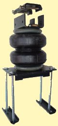
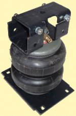
The pictures you normally see of these air assistant suspension units have brackets to mount the top of the bellows on the side of the chassis rail, however on the Sevel chassis there's enough room to mount the bellows between the chassis and the leaf spring, hence the different brackets. The bag contains all the necessary air fittings, nuts, bolts and cable ties to clip the hose up tidily.
I've loosely assembled the units to create the following photo, so that you get an idea of how its assembled without the vehicle parts blocking the view.
As you can see from the first photo, you get a box of bits. With these bits you have to assemble them your self.
Before actually working on the vehicle you need to screw in the right angle air fitting to the bellows, then fit the top bracket AFTER the air fitting, then the bottom bracket. The air fitting already has a dry sealing compound on the threads, so no need to add PTFE tape. Some of the fixing bolts also had some sealing/anti shake loose compound on them, however I added some of my own stud/thread-lock to be safe. The air fittings are made from brass, so don't try to over tightening them, otherwise they will snap off. None of the fixing screws were high tensile, again if tightened too much, they will either snap off or strip the threads. If your not experienced with tightening up fixings, do use a torque wrench to avoid over-tightening.
The first thing you need to do with the vehicle is raise the back axle. Some people would spend time jacking the vehicle up and placing it on axle stands and removing the wheels...
NEVER WORK UNDER ANY UN-SUPPORTED WEIGHTS
I took the easy route and reversed the vehicle up on to some ramps, these raised the back axle by about a foot. As this gave me plenty of working space to access the axle and springs, I didn't go to the trouble of wasting my time to remove the wheels. In fact if you do try to work from outside the vehicle without the wheels, you do have to reach past the brake drums, which isn't easy.
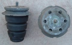
After getting the vehicle in to a suitable safe working position you need to remove the original bump stops. These are the rubber cones which sit between the axle and the chassis as shown below.
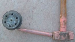
These are held in place with a single 10mm threaded stud. This is where the hammer comes in. You could use some Stilson's (large pipe grip thingies), but not many people will have access to such a large tool. Not to worry, the easiest and quickest way is to use a hammer and cold chisel (or bit of bar). You simply rest your chisel at an angle in one of the notches and knock it with the hammer to rotate the bump stop as shown below.
Although my chisel is not actually shown in the notch, you should be able to get the general idea of the operation and angle to work at. You do need to turn the bump stop the correct way to loosen it off, so when your looking at it with it hanging from the chassis, you need to rotate it so the side your looking at goes from right to left. After about half to a full turn, you should be able to turn it by hand so that it eventually spins out.
[Yes all my tools have been painted pink!! They'll shine out at any car boot ;o) ]
[Yes all my tools have been painted pink!! They'll shine out at any car boot ;o) ]
After discarding the bump stops, fit the top brackets to the chassis using the single bolt supplied (again I added some thread locking compound). Do make sure it's square to the chassis, otherwise you will encounter problems when you come to mount the bellows assembly.
With the top mount in place, you can now insert the bellows assembly between the chassis and axle. I found the gap a bit tight to compress the bellows enough to ease them into place. This is the time you will wish you had supported the vehicle on the chassis, rather than on its wheels as that will increase the gap. One method you could use to increase the gap whilst the vehicle in on ramps, is to place a scissor type jack between the chassis and spring (not the chassis and axle, as that's where you want to place the bellows!) and open the jack up to expand the gap. Since the vehicle is well supported on the ramps, it can't go anywhere, but do take care not to allow the jack to slip out whilst your operating it. The method I used to increase the gap was to use a high lift jack. Basically its a specialist jack, normally used by farmers, forestry workers and 4x4 off-roader type folks (I'll let you decide - lol) which is a ratchet jack and in my case is four foot tall. With this jack I raised the body slightly by jacking under the vehicles tow hitch.
With the bellows in position, its a simple task of inserting the top location bolts and securing to the axle and spring with the long fixing bolts and brackets. Once its all tightened down and rechecked you can install the pneumatic pipework.
If your not going to go for the extra expense of a gauge and valves in the cab, its simple enough to run the pipes from the bellows to the filler points. There's all sorts of places you can mount the fillers (not too far from the axle as only a limited amount of hose is supplied by Firestone) like drilling two holes in the bumper, or making your own bracket to mount them under it, the best place I have found is in one of the external lockers. However Mike and Carol wanted a gauge and valves in the cab, at least it will stay clean and be easily accessible.
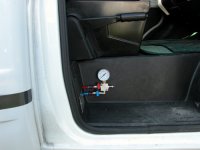
Again the valves and gauge assembly can be mounted in various places, but it was felt the best location was in the driver door foot well as shown below.
Firestone are able to supply their own valve and gauge assemblies, but none allowed for the hoses to approach the assembly from the side. I have seen quite a few, but most are mounted on their side and don't quite look right. Anyway I had supplied photos to Mike and Carol with hoses approaching vertically, but the one above was felt to be more aesthetically pleasing as the gauge was the correct way up, and with the hoses approaching from the side, it was easier to mount the assembly closer to the corner of the footwell, thus being less obtrusive.
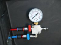
On the close up view below, I have colour co-ordinated the valves and hoses to make it easier to remember which valve operate which side of the vehicle (with road marker posts, red is always on the right, right ;o) ). The tyre inflation valve is where you inflate the bellows. I initially had the valve facing out towards you, but after testing in situ, we felt it was better as shown below.
The hose connections are real simple to use, as providing you have cut the hose reasonably square, you simply push the hose in to the fitting until it stops. To release, you have to push the coloured ring in to the fitting, then pull the hose out. They do seal extremely well, though if they do leak slightly, increasing the air pressure for a short period usually does the trick.
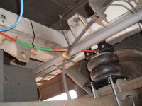
To complete the pneumatic installation, its a matter of running pipes from the bellows to the cab. I won't bore you with photos of every cable tie, however I'll run through a couple. The one below shows the hose running from the bellows to a cross member. To add protection to the hose, I ran the hose through a larger hose (green bit) to help avoid any chaffing.
To complete the pneumatic installation, its a matter of running pipes from the bellows to the cab. I won't bore you with photos of every cable tie, however I'll run through a couple. The one below shows the hose running from the bellows to a cross member. To add protection to the hose, I ran the hose through a larger hose (green bit) to help avoid any chaffing.
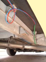
The shot below shows the run from the back of the vehicle up to the cab. Where the hoses run in to the drivers door well, I ran them through larger hoses as its twisted around various objects and through holes which I drilled to gain access to the door well. Inside the cab you will notice there is no slack hose, this can be a real pain if you need to work on the system for any reason, so to overcome the lack of slackness, I left a small loop of hose along the chassis.
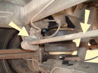
With all the pneumatics finished, the brake load sensing valve (LSV) needs to be checked and adjusted if necessary. The LSV is shown below (left arrow), and actuated by a lever (right arrow)
(The photo is of an early chassis, not a Ducato/Boxer chassis, but the LSV system is basically the same)
The LSV is plumbed in to the rear brakes and controls the amount of brake pressure applied to the rear axle. Through levers, it senses the height of the chassis in relation to the axle. With the chassis low, it applies maximum break pressure, but when the chassis is high with no load, it applies minimal pressure. The reason for this is to avoid the rear wheels locking up with no load on the chassis. If this happened going round a corner, you'll end up with a situation like a handbrake turn and find the rear of the vehicle overtaking you. With motorhomes, they are always loaded (you never go home and remove the body, or do you?) so the LSV quite often seizes up. Most MoT testers are switched on enough to realize its not an issue with motorhomes so don't worry about it.
With the semi air suspension lifting the body away from the axle, there is a chance that the LSV thinks there is no load on the rear axle and starts to limit the braking capacity. There are kits available to counteract the LSV getting it wrong, but these are generally only fitted to empty vans or flat bed trucks where the load is removed. To avoid the LSV getting it wrong on a permanently loaded chassis (as with a motorhome), you'll need to alter the LSV linkage. On the rear axle you'll find a slotted/slider adjuster, as pointed out by the red arrow below.
(The photo is of an early chassis, not a Ducato/Boxer chassis, but the LSV system is basically the same)
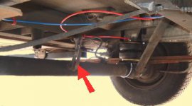
(View from front of vehicle, towards the rear axle)

(View from front of vehicle, towards the rear axle)
(The photo is of an early chassis, not a Ducato/Boxer chassis, but the LSV system is basically the same)
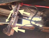
(This photo is a close up of what's pointed out in the photo above)

(This photo is a close up of what's pointed out in the photo above)
If not already done, as was this vehicle, you need to loosen the fixing screws in the middle of the slider, and move the two halves apart as shown above. If your unsure of this, and its effect on the brakes I thoroughly recommend you pump up your suspension to its highest position and have your brakes tested at a MoT station (Not sure, but I don't think there is a charge for this), then at least you'll know whether its set correctly or not.
That completes your installation, and your system is ready to use.
That completes your installation, and your system is ready to use.
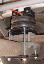
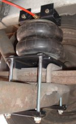
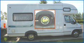
The two photos below show the same bellows deflated, not fully because the spring is still capable of providing support to the chassis. Then to the right, inflated but not to capacity.
Unfortunately my photography skills don't show the finished result to its best, perhaps if the vehicle was a dark colour I may have stood a chance at showing the rear wheel arches to their best. Mike even tried with the shots below, we did discuss merging a high-lighted wheel on top of the original, but I've chickened out for now and placed a high-lighted section within the main photo.
Anyway the first photo below shows the vehicle with the wheel sitting inside the wheel arch, where as the lower photo has a clear gap between the wheel and arch.
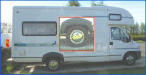
The differences above may not seem sufficient, mainly due to the limited effective expansion length of the bellows, but the effective pressure the bellows can apply between the chassis and axle is quite significant, thus lifting the body back into its original ride height.
Putting the ride height to one side, everyone who has had air assisted suspension systems fitted to their vehicles all say they are impressed with the improved ride, improved cornering and less prone to side winds and buffering by large HGV's
If your interested in fitting the above to your own vehicle, we can supply them via our on-line shop. Costs vary, but for a Fiat Ducato/Peugeot Boxer/Citroen Jumper 1994 onwards we can supply them for £299 (without gauge and valves, but including delivery)
A good starting point for what pressure to inflate your air springs to, try 40psi and experiment up and down from there.
Always have a minimum of 5psi in the air spring when not being used for long periods.
DON'T jack up the body with any pressure above 5psi in your air springs (jacking up the axle will be fine).
Disclaimer
The information provided on this Website site is offered with no warranty as to the authenticity, suitability or competence of the individual, company or service quoted here in. This Website shall not be liable for any damage or difficulty, direct or indirect, arising from utilisation of the information contained within these pages.


