Technical Becky's leaky strut

Currently reading:
Technical Becky's leaky strut

I've been following this thread with interest, as I knew my top mounts were getting old. (I've had a box of new ones on the shelf for a few years now!)
So yesterday morning I lifted the bonnet to check the levels, and whilst there, glanced into the chamber below the screen, check the fish are ok, etc., and across to the suspension tops. Oh dear! Left one further back than the right.

This morning, off with the legs. Struts not leaking, but looking rather rusty. Springs quite good, but some paint starting to crack.
Time to change the lot then. (Jock has started an epidemic)

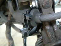
I love the little clips that hold the brake hoses, but they are past their best, and appear to be about £7 each, so tiny cable ties will do that job.

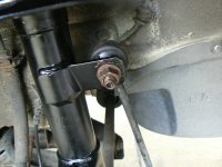
Strut bottom bolts are fed in from the back, but you know that now.

Top nuts came off easily.
Strut bottom bolts came out easily, but have ordered new ones, threads and heads looking all of their 13 years.
Anti-roll bar links fought back. Shame as they are not that old. Tiny hex inside each thread poor and won't hold. So they've come out with the struts, as the bottom nuts, arguably more exposed, came off without a fight.

Seems Jock has taken the last springs from S4P. Had to pay a little more for Lesjofors ones from Autodoc.

Life savings spent. All the bits should be here by Friday, so will rebuild then, busy until then anyway.

Time for a service too, including another cambelt as time has passed. Could be easier doing the cambelt with no suspension strut in the way.

At times like these, it is good to have two cars. So it'll be the Skoda all week.
 
Well done Jock!!!

Dead right about those springs. It's worth putting a ratchet strap on each side just in case a spring clamp slips.

Personally I'm more worried when working on old springs in case a rust pit causes a coil to fracture. If you are fitting new - I think there's a case for cutting the old spring with an angle grinder slitting disc rather than trying to compress it.
 
Aye Jock, I always like to see the new shiny things going on to a car, & you have the added satisfaction you did this yourself. Still some mechanical work/knowledge left in us oldies yet......:D

I try Jim, I try! Don't think I'll be making much bonus though! Two and a half days to change two struts? Laughable!

I love the little clips that hold the brake hoses, but they are past their best, and appear to be about £7 each, so tiny cable ties will do that job.

Anti-roll bar links fought back. Shame as they are not that old. Tiny hex inside each thread poor and won't hold. So they've come out with the struts, as the bottom nuts, arguably more exposed, came off without a fight.

Seems Jock has taken the last springs from S4P. Had to pay a little more for Lesjofors ones from Autodoc.

Life savings spent.

Great minds think alike where the little "butterfly"? clips are concerned. Mine weren't there on either side! So:

P1080615.JPG

I rather like this solution. Think I'll just live with it.

Anti roll bar drop link nuts? Mine wouldn't undo using the Allen key either. I've run into this before and found that if you push the gator back you can get a small Stilson, Footprint, or your favorite choice, onto the back side of it whilst you work at unscrewing the nut. I did it this time on the O/S (N/S was compliant) but then found that although I got the gator back into it's groove quite easily I just couldn't get the "rubber band" back over the gator to seal it. After quite a few tries I gave up and used a bit of galvanized tying wire:

P1080614.JPG

Whilst we're on about these links Mine needed a 16mm socket to fit. Not a very common size?

P1080616.JPG

I thought I'd run a die down the thread but found it's not a common metric thread - in fact I nearly mucked it up with a standard die! couldn't find a tap to fit the nut either. Maybe it's a metric fine (which you don't find often so I've never bought any taps/dies in this thread form) Anyway I reclaimed it by smearing a little valve grinding paste on it and working the nut on and off, on and off, on and off, etc. Ended up feeling really nice! Just thought, it's been years since I ground a valve in!

Sorry If I hogged the last springs. Interesting to see different springs for Aircon and non aircon versions. I wouldn't have thought there was enough extra weight to need this? Autodoc did me a very good price for the belt kits (Gates) I bought for both Becky and my older boy's Punto (Same belt kits of course) I think they were around the £60 mark for "with pump" kits?

Well done Jock!!!

Dead right about those springs. It's worth putting a ratchet strap on each side just in case a spring clamp slips.

Personally I'm more worried when working on old springs in case a rust pit causes a coil to fracture. If you are fitting new - I think there's a case for cutting the old spring with an angle grinder slitting disc rather than trying to compress it.

Well there you go Dave. This is what's so wonderful about this (our) forum. I'd never thought of putting a ratchet strap on as a safety back up. Also I've never considered that an old spring might "let go" when being compressed. What a very good point. I'll be a nervous wreck next time!
 
Today has been "set up" day. When I checked Becky over before starting on the struts I measured the toe setting using my "trusty" home made tracking gauge. Whenever I'm doing anything on a car I like to know where things stand before I start. Then if there is an unexpected outcome it gives me a reference for checking. (one reason I always do a whole vehicle scan with MES first off when I'm doing a service). The result I got was that she was toed out around four and a half to five mm. Recommended setting is parallel - ie Zero mm.

Before I start in here can I recommend that anyone wanting to fully understand what I'm talking about types in "Jock's tracking gauge" into the search bar at the top of the page and read the thread. If you're just being entertained by this post, by all means read on. - let's call Jock's tracking gauge "JTG" from here on.

I'm now going to try to set up the toe on Becky. First thing is a very thorough examination of suspension and steering components (more in JTG). Assuming all is found to be ok next is to check the wheel rims (or perhaps wheel "lands" - the bit of the wheel the tyre bead sits on) run "true" when the wheel is rotated. This is the datum point from which your readings are taken, if the wheel "wobbles", for what ever reason. (see JTG) when rotated you have no chance of obtaining accurate readings and will just be wasting your time to even try.

Here's me checking Becky
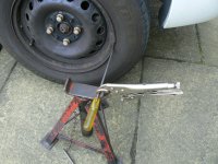
P1080623.JPG

The screwdriver (or whatever you want to use) is clamped securely to the stand, placed so it lightly rubs against the wheel rim and the wheel is rotated. The wheel must run true. If it doesn't either try the land - in which case you will use this for your datum reference or swop another wheel to this position and try again. When you've got a satisfactory wheel on both front hubs put the car back on the ground (you had to jack it up to spin the wheels of course) and go a run round the block to settle the suspension down. If you find most of the rim runs "true" but a small are does not then just mark it (I use blackboard chalk) and you can still use that wheel as long as you don't involve the chalked area.
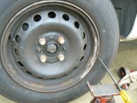
P1080626.JPG

Now approach your chosen flat surface where you are going to take the measurements. The car must be driven forward and brought to a halt without running backwards so that all forces acting on the suspension are as they are when you are driving along. The "fixed" end of the tool is now locked up with the end in line with the centre of the axle and a distance piece cut to the same length (I used a piece of doweling). It's very important that this fixed end is locked off securely. If it moves your readings will be nonsense.
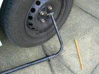
P1080629.JPG

Now the whole tool is slid under the front of the car. The fixed end is on the right here (N/S and it's stop end is placed against the outer wheel rim (or land if you've chosen that as a datum point)
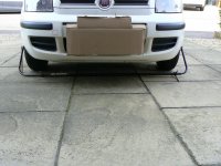
P1080628.JPG

Now the sliding end is placed against the outer rim of the other (O/S) front wheel, using the distance piece (doweling) to get it to exactly the same height as the fixed end on the N/S. This is very important as wheel camber will make a nonsense of any readings you take if both heights are not identical.
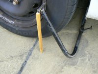
P1080631.JPG

Now slide the marking cursor along until the scribing line is over the piece of masking tape (more in JTG) and securely lock it off. As with the fixed pointer, if this subsequently moves your readings are toast! Now take a sharp pencil and, holding it at right angles to the masking tape (to avoid parallax always hold the pencil at right angles) make a line on the tape.
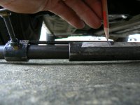
P1080627.JPG

Now "wheech" the whole tool out from under the car - careful not to bang either of the lock off clamps - and slide it in behind the wheels. Now the fixed end is going to be on the O/S and the sliding end on the N/S. Repeat the whole exercise. A lot of care is needed to be sure that both ends of the tool are in contact with the wheel rims before scribing your line and I always make some sort of mark to remind me which line is the "in front line" and which is the "behind line". Now "wheech" the whole thing out and have a look at your lines. The first result I got was this
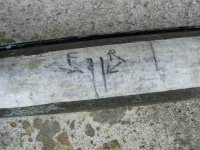
P1080633.JPG

Which shows the wheels to be toed out by around 4 to 5 mm - obviously been like this since I bought her. Mr Haynes tells me it should be zero (parallel). So, as she's set up just now the N/S (LH) wheel is trying to go slightly left and the O/S (RH) wheel is trying to go slightly right. I would expect to see the front tyres with excessive wear on the inside shoulders if she's run for any length of time like this but the dealer had put a new tyre on the left front and swapped the best of the rest to the right front so I couldn't really check but, interestingly one of the rears looks like this
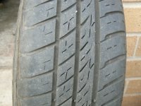
P1080653.JPG

Bet it was on the front before he messed about with it for sale. Dealers will often put the best tyres on the front because if you stop on his forecourt with the steering on a lock the tread looks good!

To get rid of all this unwanted toe out we need to adjust the effective length of the track rods (which connect the ends of the rack to the track rod ends.) They are threaded into the trackrod ends and secured with a lock nut (often corroded nearly solid) the end in the rack is a ball joint so can spin round as you turn the track rod itself (after slackening the lock nut)
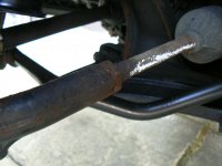
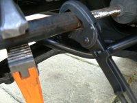
P1080646.JPG

P1080645.JPG

On the Panda the rack is behind the centre line (axle line) of the front wheels so the track rods need to be screwed out of the trackrod ends a wee bit. But by how much and do both need to be turned the same amount? Well the first thing to find out is whether the steering wheel is centred on the rack. Do this (I like to have the front end off the ground to minimise stress on the steering components) by sitting in the drivers seat, turn to full lock (doesn't matter which way) and make a wee mark (I like blackboard chalk because you can rub it out easily) on the wheel at 12 o'clock and also, in the same position, on the top of the instrument binnacle. Now go to full lock the other way and mark the wheel, wherever it stops, opposite the binnacle mark. You now have two marks on the wheel and know how many turns it took to get there - half way between is the straight ahead position OF THE STEERING RACK. If the wheel is correctly fitted to the column, with THE RACK in this position the steering wheel should also be straight ahead. If it's not you've got a problem and I'm not dealing with that here. Your steering needs to be centred like this before you start adjusting toe if you are to end up with the wheel straight when you're going straight!

Next thing to check is whether, with the rack centred, both wheels are pointing ahead on equal angles. to do this you need a long straight edge. It doesn't need to be microscopically straight but it does need to look straight without any obvious bends/kinks. I use a length of Dexion but a nice straight plank will do just fine. If you.ve had the car up in the air doing your checks you'll need to go round the block again and end up rolling forward to a stop with the STEERING WHEEL STRAIGHT AHEAD. now put your straight edge down one side of the car with one end on the forward sidewall of the rear tyre and the other right across both edges of the front tyre
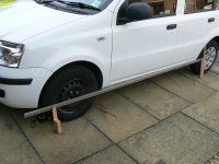
P1080641.JPG

So that you can see the contact between the front and rear sidewalls - keep the other end of the straight edge in touch with the front sidewall of the rear tyre whilst doing this.
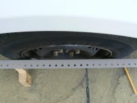
P1080642.JPG

As you can see the result for Becky is that it's touching both front and rear. Note this (measure any gap and whether it's front or rear) and repeat the exercise on the other side. If the steering is properly centred you should have, with the steering wheel in the straight ahead position, an equal result on both sides (N/S mirror image of O/S) and this is what we get on Becky so that's a good start. But the straight edge is touching both front and back on both front tyres and we know we've got a measured toe out of around 4 to 5 mm. How can this be? surely we should be seeing a gap at the rear sidewalls on both sides because with the setting toed out the front left wheel is going slightly left and the front right is going slightly right? The answer is really quite simple. The front track is wider than the rear (that means that measured across the car the front wheels are further apart than the rears!
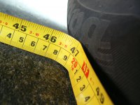
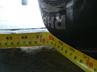
P1080639.JPG

P1080640.JPG

Think about it for a minute and you'll get it. Ok so Becky's steering is centred and both wheels are pointing out by the same amount so we need to turn them in towards each other by identical amounts on each side. If the straight edge check shows a difference side to side then you'll have to adjust one side more, or less, than the other to equalize them. So, on Becky, I now slacken the lock nuts on the track rods and turn both sides so as to move the track rod ends out (effectively making the arms longer). How much by? good question. It's very much "suck it and see" but as you do it more often you get a feel for it. I choose to rotate each arm three quarters of a turn. Mark the arm with chalk before you start, it's very easy to get confused and loose your perception of how much you've twisted the arm. Watch also that you're not twisting up the steering rack gator. You may need to slacken any clips if fitted and a squirt of something like WD40 helps it to spin without gripping the rubber. Now lightly lock up the lock nut - to eliminate any backlash in the threads - and do your toe measurements again. I found I'd gone from around 5mm toe out to just under 1mm toe in.
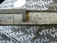
P1080652.JPG

Slacken the lock nuts (that's why you just "nip" them up during adjustment so they are going to slacken easily) and a wee turn in the other direction - I went less than a quarter turn - lock it all up lightly again and remeasure. Both pencil marks are now coming out on top of each other so I'm now at parallel! Yippee!
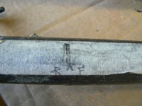
P1080647.JPG

That was quite an easy one, I've sometimes spent hours doing these adjustments where the wheel is not centred on the column and someone has made unequal adjustments side to side to compensate when what they should have done was centre the wheel on the column before doing anything else. I notice cars with EPS are tending to have a column with one master spline so the wheel will only fit in one position - Halleluja!!!

Now lock the track rod nuts up good and tight and give them a good slaistering with Coppaslip so they'll be easier to undo next time.
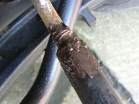
P1080654.JPG

Lastly, do the straight edge check again. Steering wheel straight. gaps should be equal mirror images on both front wheels. but prehaps it's easier to just go a drive down the road and see if the steering wheel is centred when you are going in a straight line. If it's not you have my permission to turn the air blue (I've been known to) because you're going to have to go back and "fiddle" some more. If you've taken care and done it right though this method works every time.

Still think those bolts are needlessly long though?
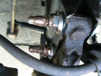
P1080655.JPG

I am particularly pleased with the way Becky sits now. No longer does she suffer front end "droop" Ride height - Axle centre vertically to wheel arch - on the front wheels before was 342 mm on the N/S and 345 mm on the O/S. Now, after a good run around and a few, gently negotiated, speed bumps she sits at 360 mm both sides.

P1080656.JPG

What a handsome lass she looks!
 
To get rid of all this unwanted toe out we need to adjust the effective length of the track rods (which connect the ends of the rack to the track rod ends.) They are threaded into the trackrod ends and secured with a lock nut (often corroded nearly solid) the end in the rack is a ball joint so can spin round as you turn the track rod itself (after slackening the lock nut)

View attachment 201968

View attachment 201969

Just having a quick reread of this and I think it's important to mention that when you are trying to slacken the lock nut on the track rod you must not rely on the track rod end to resist the twisting forces you are applying. You'll notice that in the second illustration I've got a hefty Stilson type wrench (orangy yellow) on the track rod end to resist the turning forces as I heave on the lock nut with the other spanner. I've seen track rod ends heaved right off their ball ends and even if that doesn't happen substantial internal damage is likely if you don't support the track rod end with a pretty hefty tool. So the possibility of doing serious and potentially dangerous damage is significant.
 
Well done with the multi-quote.
Great tracking explanation. My paving slabs are moving a little, so need lifting and resetting, so I thin kfor the tracking, I'll just lob it at the local garage for a 4-wheel laser alignment. Nice to have a garage you can trust at the bottom of the road. 200 yards and I can walk home.
The anti-roll link threads are 10mm x 1.25. Standard is 1.5. Been looking for a source of new nuts, but they are a bit special. They are apparently called carp nuts, but can only find standard thread. So I've spend a bit of time in the garage and rescued them. Struts now dismantled. I liked the advice about springs breaking. My compressors are Draper with a double claw at each end, so hold firmly.
 
Well there you go Dave. This is what's so wonderful about this (our) forum. I'd never thought of putting a ratchet strap on as a safety back up. Also I've never considered that an old spring might "let go" when being compressed. What a very good point. I'll be a nervous wreck next time!

I don't get too stressed about it. If the springs are good enough for reuse, they'll be fine on the spring compressors. If the springs look rough and are being replaced anyway it's quicker to slice the grinder through them.


Drop link nuts get the same treatment. Slice straight across and lever out the fragment. I always smear anti seize over the exposed threads and into the end hex. A thought about yours rounding off and the threads being funny - they might be UNF or UNC threads which would have an imperial size socket hex in the end.
 
Well done with the multi-quote.
Great tracking explanation. My paving slabs are moving a little, so need lifting and resetting, so I thin kfor the tracking, I'll just lob it at the local garage for a 4-wheel laser alignment. Nice to have a garage you can trust at the bottom of the road. 200 yards and I can walk home.
The anti-roll link threads are 10mm x 1.25. Standard is 1.5. Been looking for a source of new nuts, but they are a bit special. They are apparently called carp nuts, but can only find standard thread. So I've spend a bit of time in the garage and rescued them. Struts now dismantled. I liked the advice about springs breaking. My compressors are Draper with a double claw at each end, so hold firmly.

I myself, many years ago, wondered if my slabbed drive would be level enough to accurately take readings and I found a really flat piece of ground at the lockup garages across the road which worked well but i was sometimes disturbed by a neighbour wanting access to their garage. Especially annoying if you were in the middle of an adjustment. Then it occurred to me that if I could replicate the ride heights measured on the level ground when the car was on my drive that would prove the slabs were level enough (after all I do accept my primitive gauge is not as hair splittingly accurate as a Hunter bench!) So I measure the ride heights on the level ground and then again on the slabs and guess what? So near to identical as to be not worth worrying about. (I made small - only I know they are there, Shhh, don't tell Mrs Jock - marks on the slabs so I could always "hit" the same spots in future) so now I just do it on the slabs and it seems to work Ok as tyre wear patterns look fine.

Interesting about the nuts with captive washers. Wonder why they went for the fine threads? Oh, also wonder if the guy that designed them was keen on fishing (Carp?).

Yes, Dave's advice about the springs brought me up short. I've never heard of this happening but could well imagine it might. I'm going to modify my compressors to incorporate retainers on the hook ends - probably a good excuse to get the welder out. I like a bit of violent welding from time to time!
 
Last edited:
I broke a front road spring on the Espace. The broken end was like a spear and it took the tyre with it.

That damage was done by a road impact, but seeing that shattered fragment gave me a lot of respect for clamping up road springs. New springs OK, but old and rust pitted, being replaced anyway, just leave on the old strut and chop a coil though with a grinder.
 
After lots of other priorities, I'm at last out in the garage building up my new struts.
First hurdle, assembling the gaiters, this is hard work. Referring back to Jock's post, I see he's had to fit them from inside, so I'll have another go before the tears prevent me from seeing what I'm doing.

Original gaiters are rubber, the replacements are plastic. Good for longevity, although the originals are still in one piece, and could be re-used, so longevity not an issue. Plastic of course is much less flexible than rubber, hence a lot of difficulty fitting the bumpstops into them, as they refuse to expand over the bumpstop. Pure genius.

Edit: The answer is - hot water.
I've seen soaking in hot water recommended for many such things, but never had any success with it, apart from scalding myself.
Found a deep baking tin, no worries if later unusable, put onto stove and simmered gently.
Introduced the gaiter and bumpstop with their relevant ends in the water, moved a little from time to time to prevent burning. Once almost too hot to handle, lifted out and pushed bumpstop into the gaiter correct way around, and with only a little grunting and swearing it went in.
First strut now built, time for lunch.
 
Last edited:
Edit: The answer is - hot water.
I've seen soaking in hot water recommended for many such things, but never had any success with it, apart from scalding myself.
Found a deep baking tin, no worries if later unusable, put onto stove and simmered gently.
Introduced the gaiter and bumpstop with their relevant ends in the water, moved a little from time to time to prevent burning. Once almost too hot to handle, lifted out and pushed bumpstop into the gaiter correct way around, and with only a little grunting and swearing it went in.
First strut now built, time for lunch.

They really are a pig to do aren't they. I tried the boiling water treatment without success but only heated the gator (not sure about spelling?). When you heated the bump stop did it soften too? If so that would help a lot. Hope the rest of it goes smoothly for you
Regards
Jock
 
They really are a pig to do aren't they. I tried the boiling water treatment without success but only heated the gator (not sure about spelling?). When you heated the bump stop did it soften too? If so that would help a lot. Hope the rest of it goes smoothly for you
Regards
Jock

The way they bite when they refuse to go in, your spelling works fine.

I used a quite shallow pan, and heated both the gaiter, just the end for the bumpstop, and the bumpstop, again the end that goes in the gaiter. Being warm and wet, they went together quite well. With the excitement of the first one, I scampered to the garage and brought back the second one, had it together in minutes.

Both struts built and ready to go into the car, job for tomorrow afternoon, weather permitting.
 
Back
Top