So as some of you may know, Fiat made a third brake light for the later cars sometime around 1999. They manufactured kits for retrospectively fitting them. The kits apparently include everything you need, but are no longer in production. The kit part no is: 5909643. If like me though you dont have a kit, you will need to know what you need to buy and do. Lets begin. The parts listed below are available at Fiat Dealerships unless otherwise stated as of 2017
Parts Required:
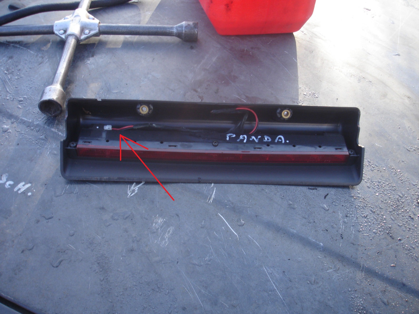
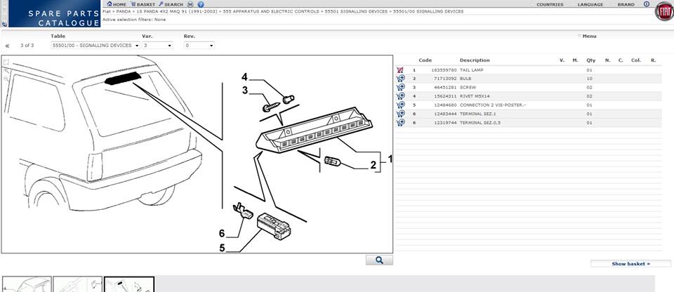
1 x Third Brake Light - 165559760 (NOT AVAILABLE FROM FIAT, SOURCE FROM BREAKING CAR ABROAD. FRENCH EBAY SEARCH TERM IS "FEU STOP" AND ITALIAN SEARCH TERM IS "TERZA LUCE" PRECEDED BY FIAT PANDA IN BOTH CASES. ASK FOR AS MUCH WIRING FROM THE CAR AS THEY ARE WILLING TO GIVE YOU, THE CONNECTOR AND THE POSITIVE AND NEGATIVE ARE VERY HELPFUL.
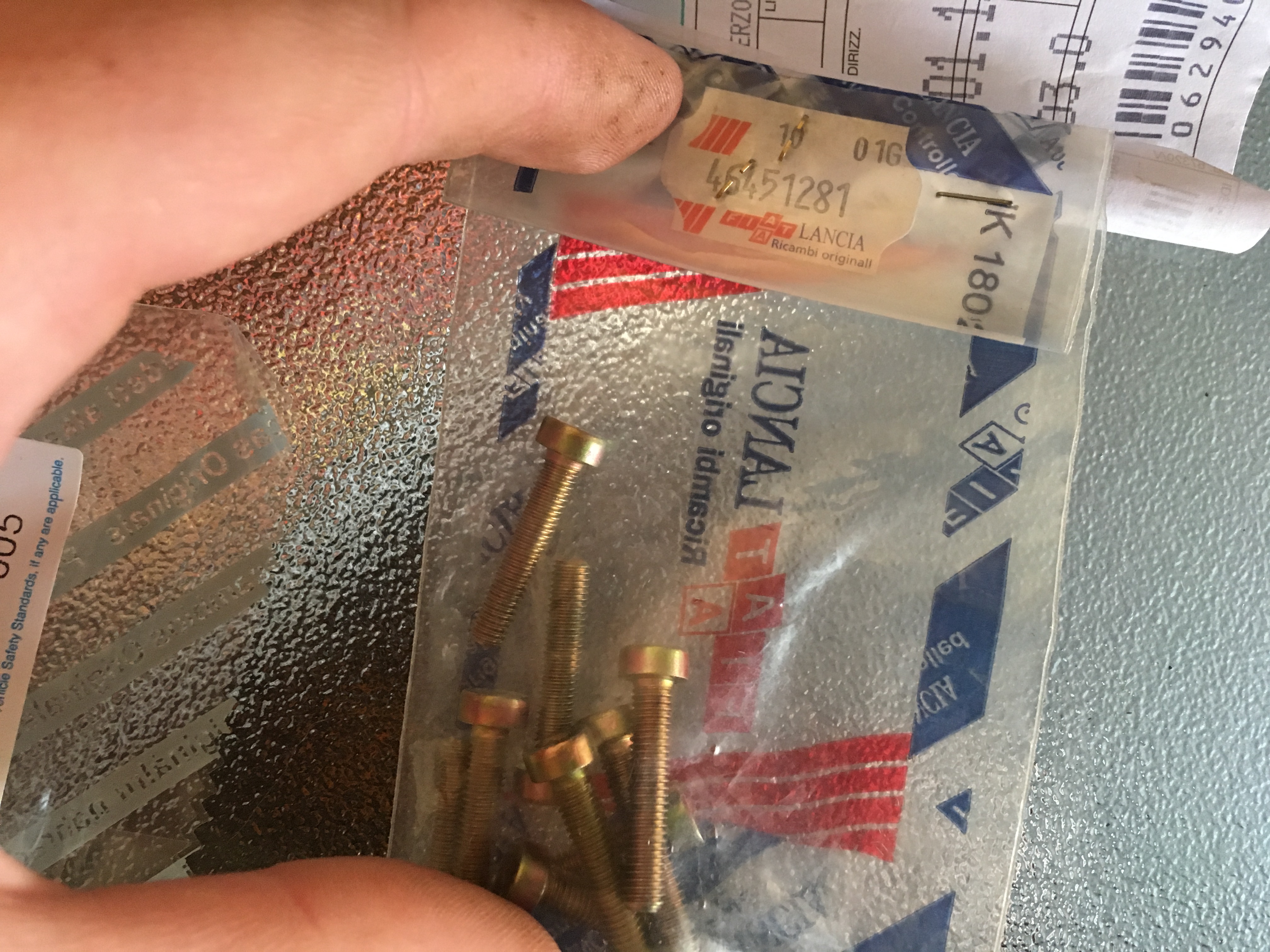
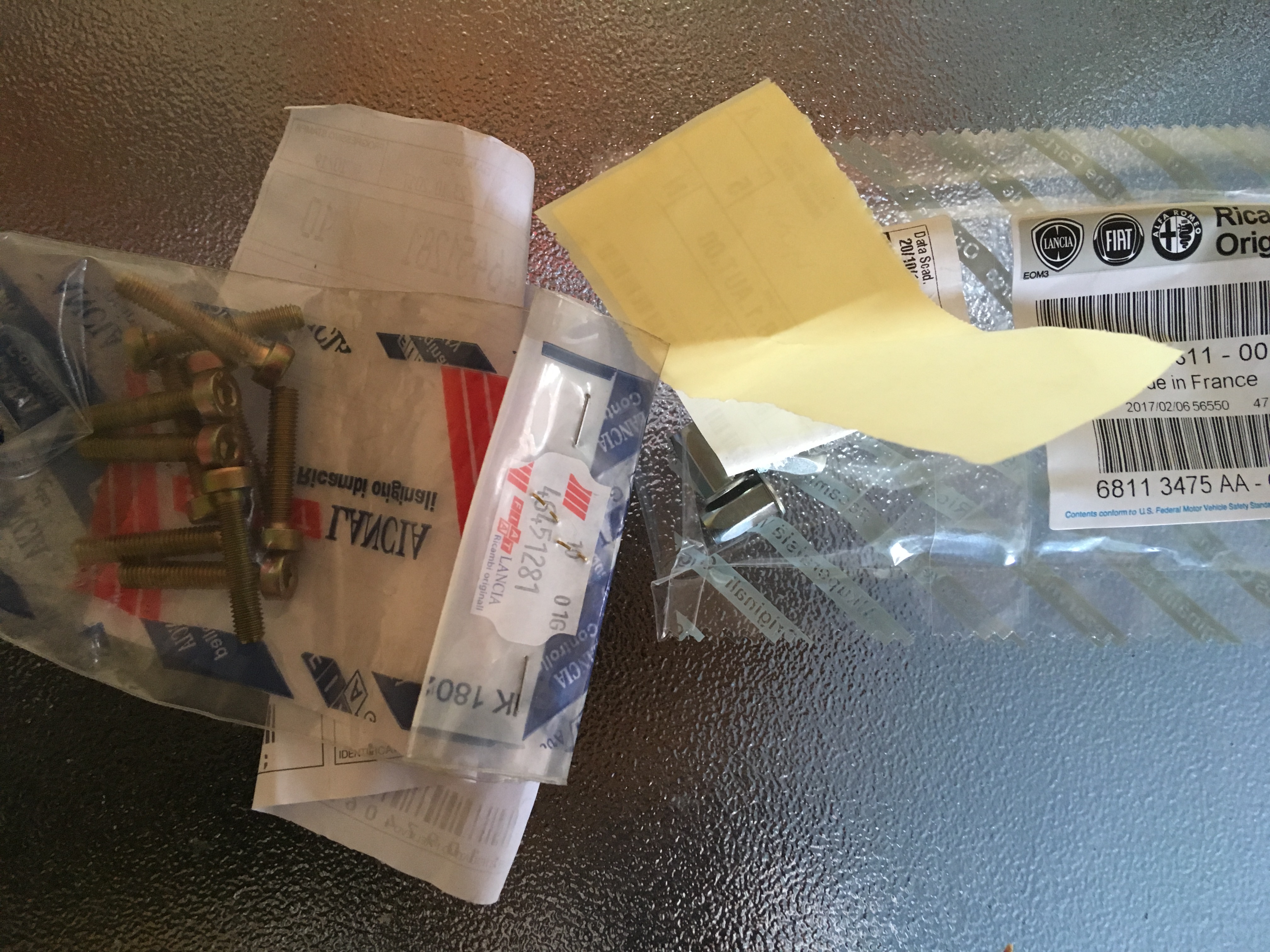
2 x Screws Part No - 46451281
2 x Rivnuts Part No - 15624311 (M5 x 14)
2 x Wire Connector Blocks of Choice
10 x Bulbs Part Number- 71713092 (2.3w wedge type, though LED equivalents are available)
5 Amp Cable Red - Halfords HEF 711
5 Amp Cable Black - Halfords HEF 712
Insulating Tape, also at Halfords and other car electrical suppliers
Optional Parts if Wiring not included-
Connection 2 Vie Poster Part No - 12484680 <white connector block which goes into light unit)
Terminal 1 - 12483444
Terminal 2 - 12319744
Tools Required-
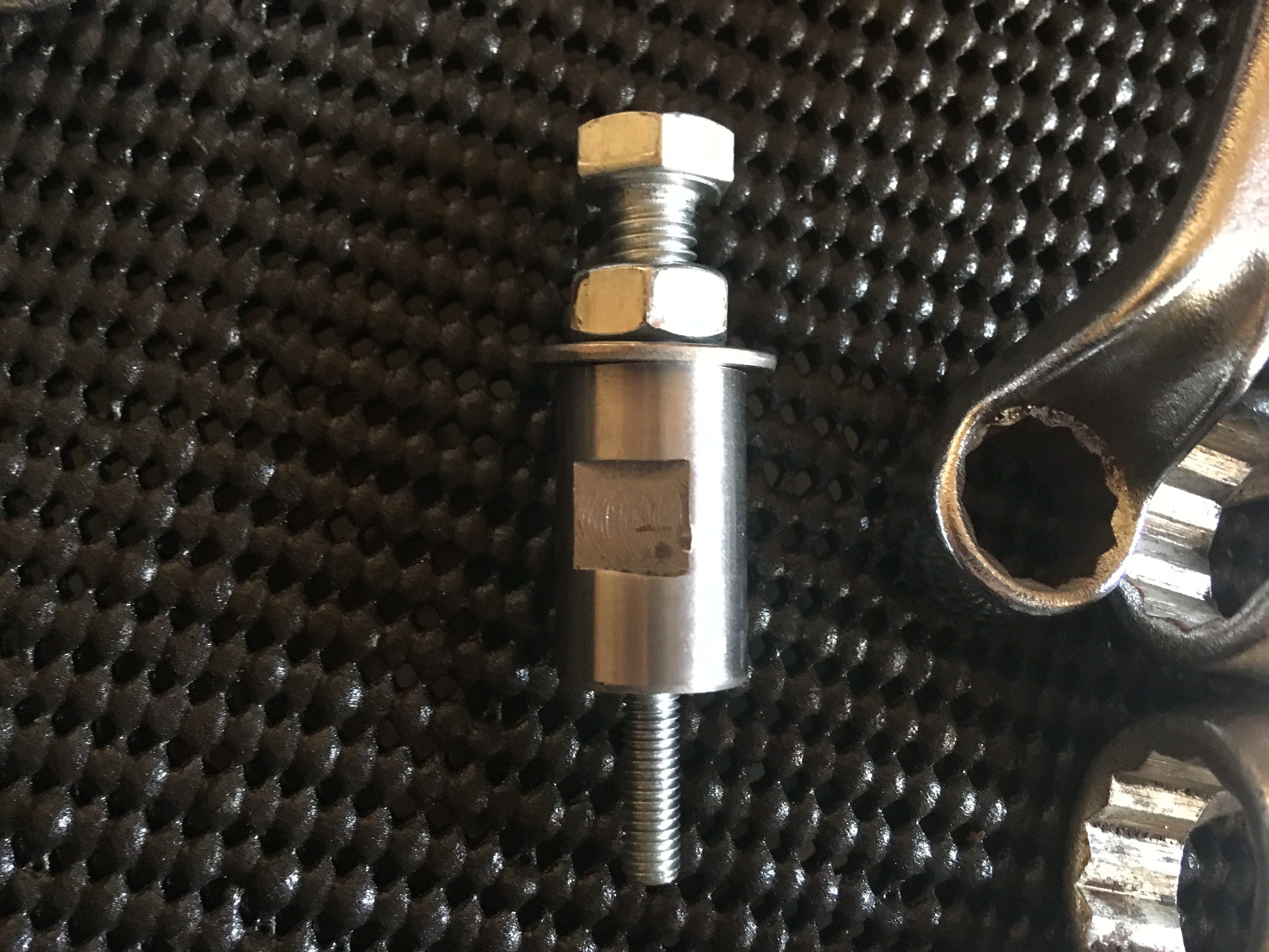
M5 Rivnut Tool
Voltage Meter
M8 Metal Drill Bit
Drill (Cordless with Plenty Charge preferred as more room without cord)
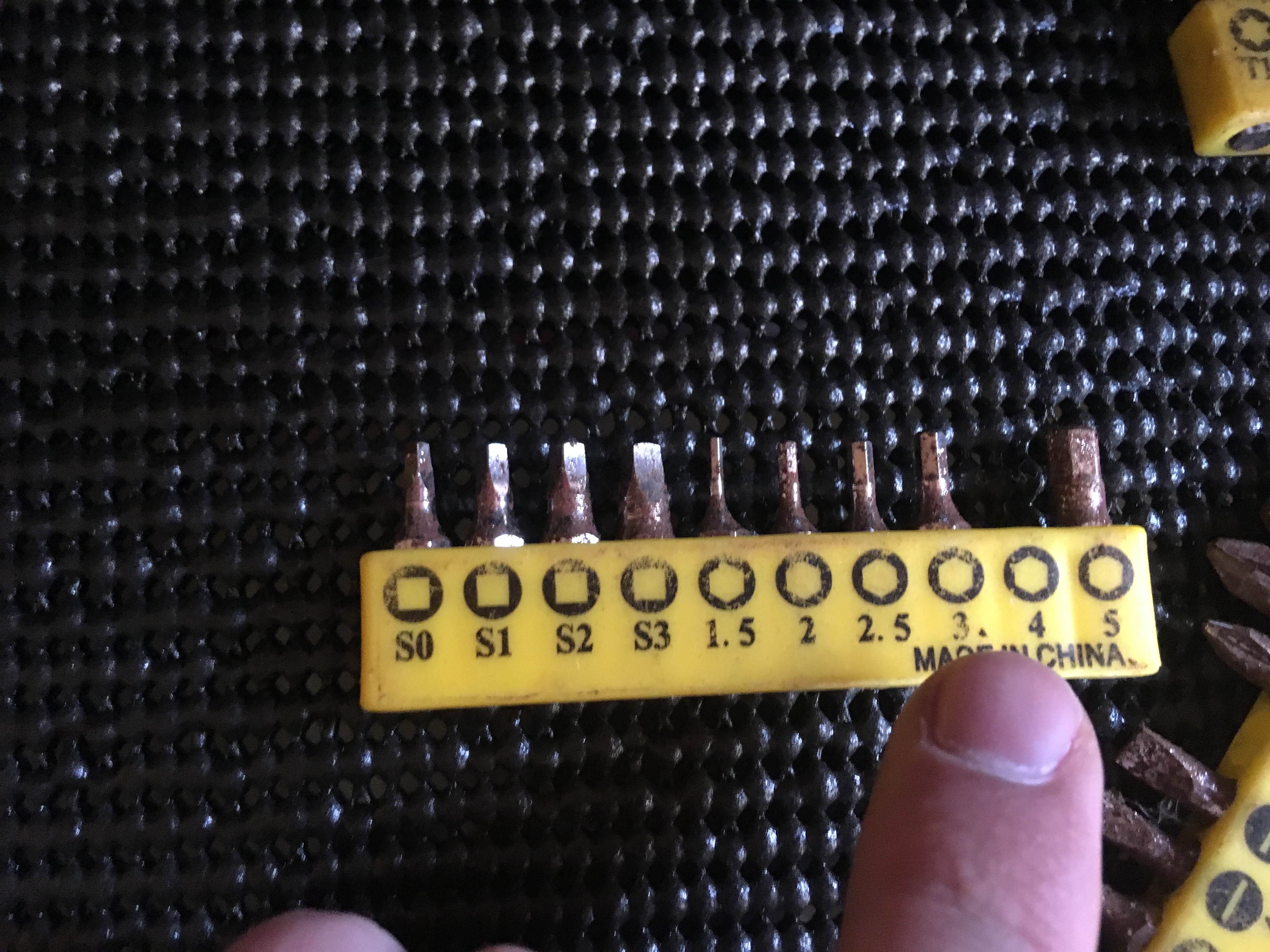
Flathead Screwdriver/Phillips head screwdriver (Supplied Toolkit one is ace)
Wire Stripping and crimping tool
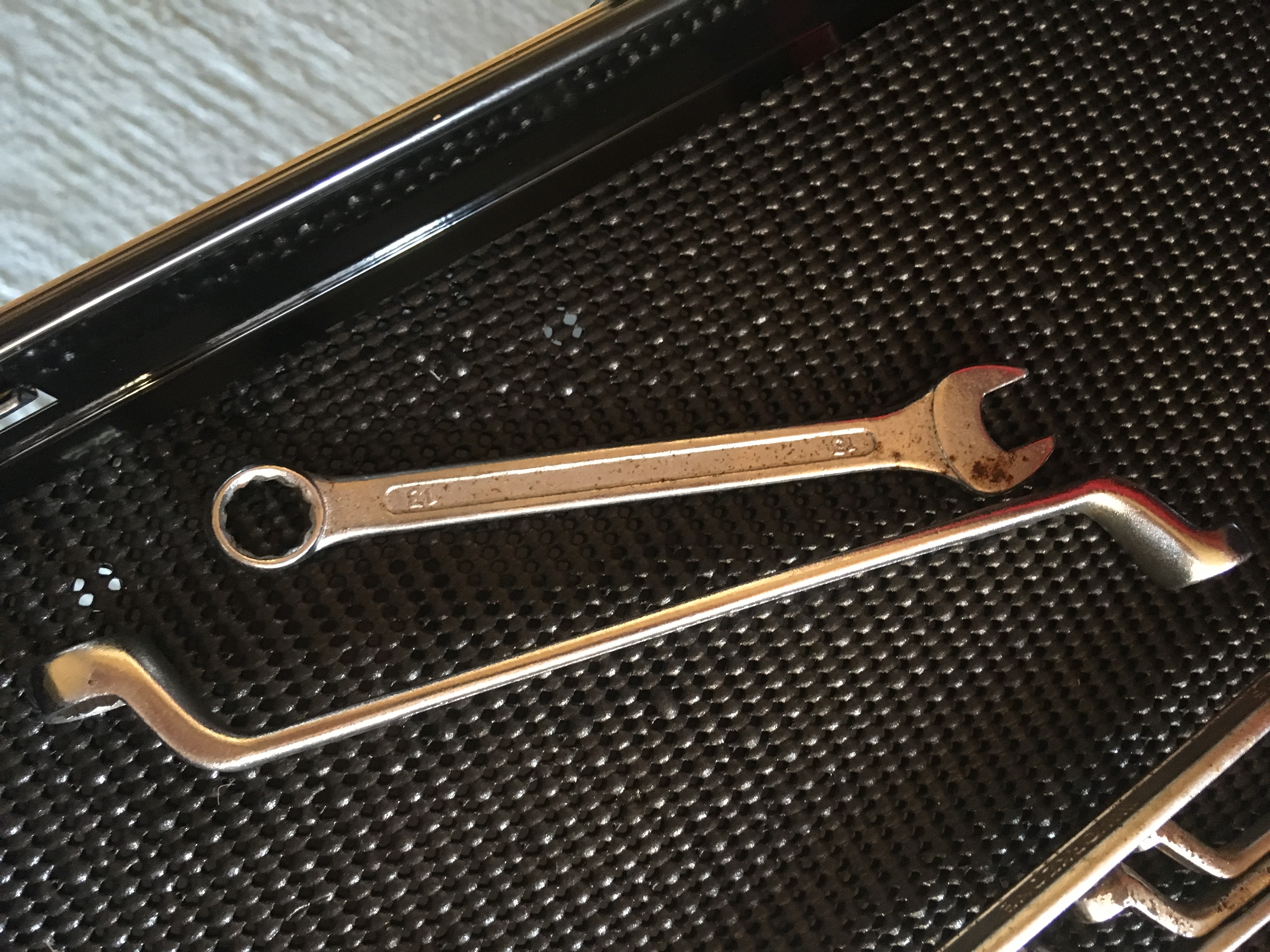
2 x 13mm spanner, open face for body of tool and swan neck (or open face) for tightening nut
Allen Key size 4
Measuring tape
Haynes Manual (To block light coming through rear window obscuring the work area haha)
Step 1 -
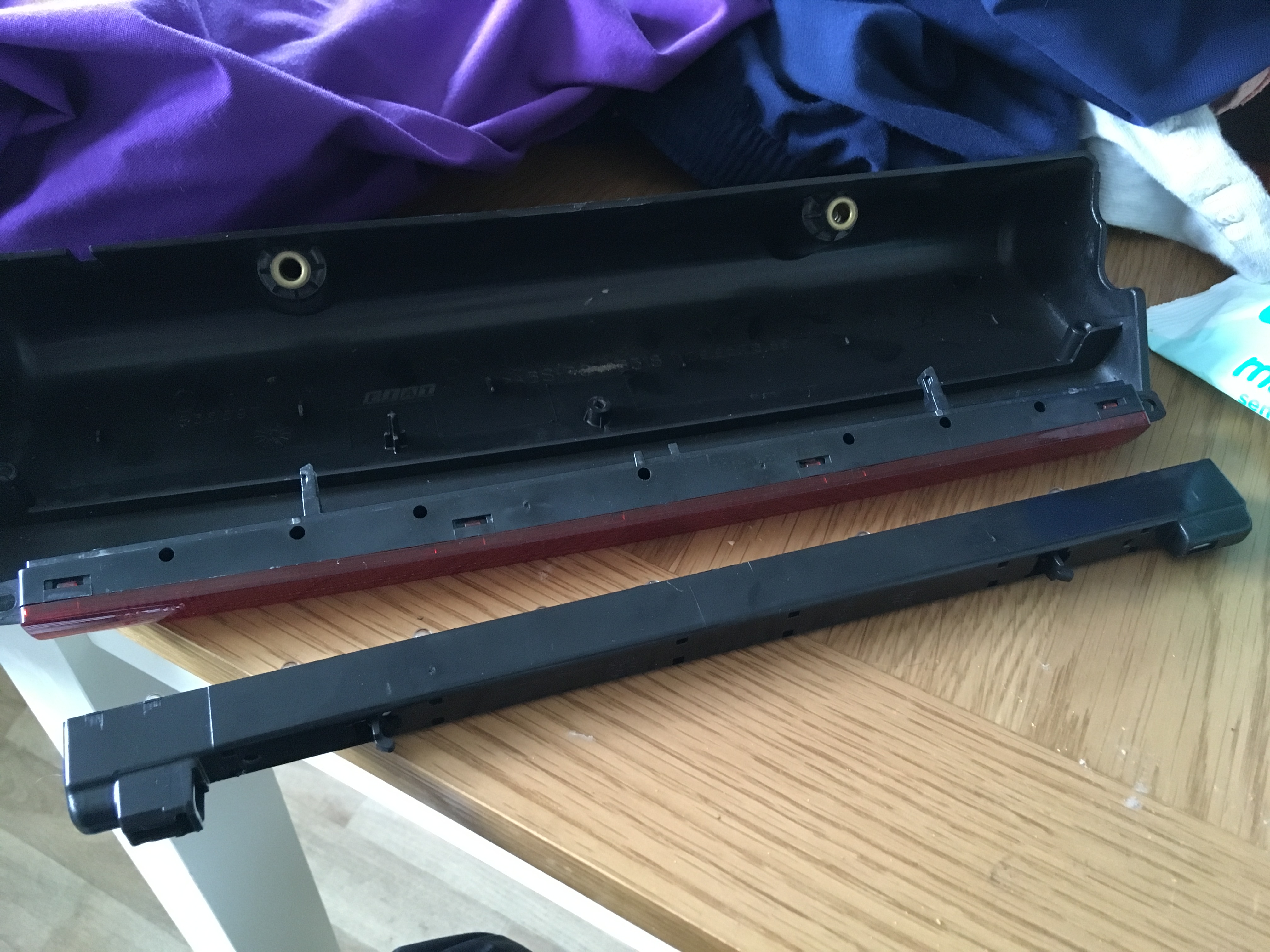
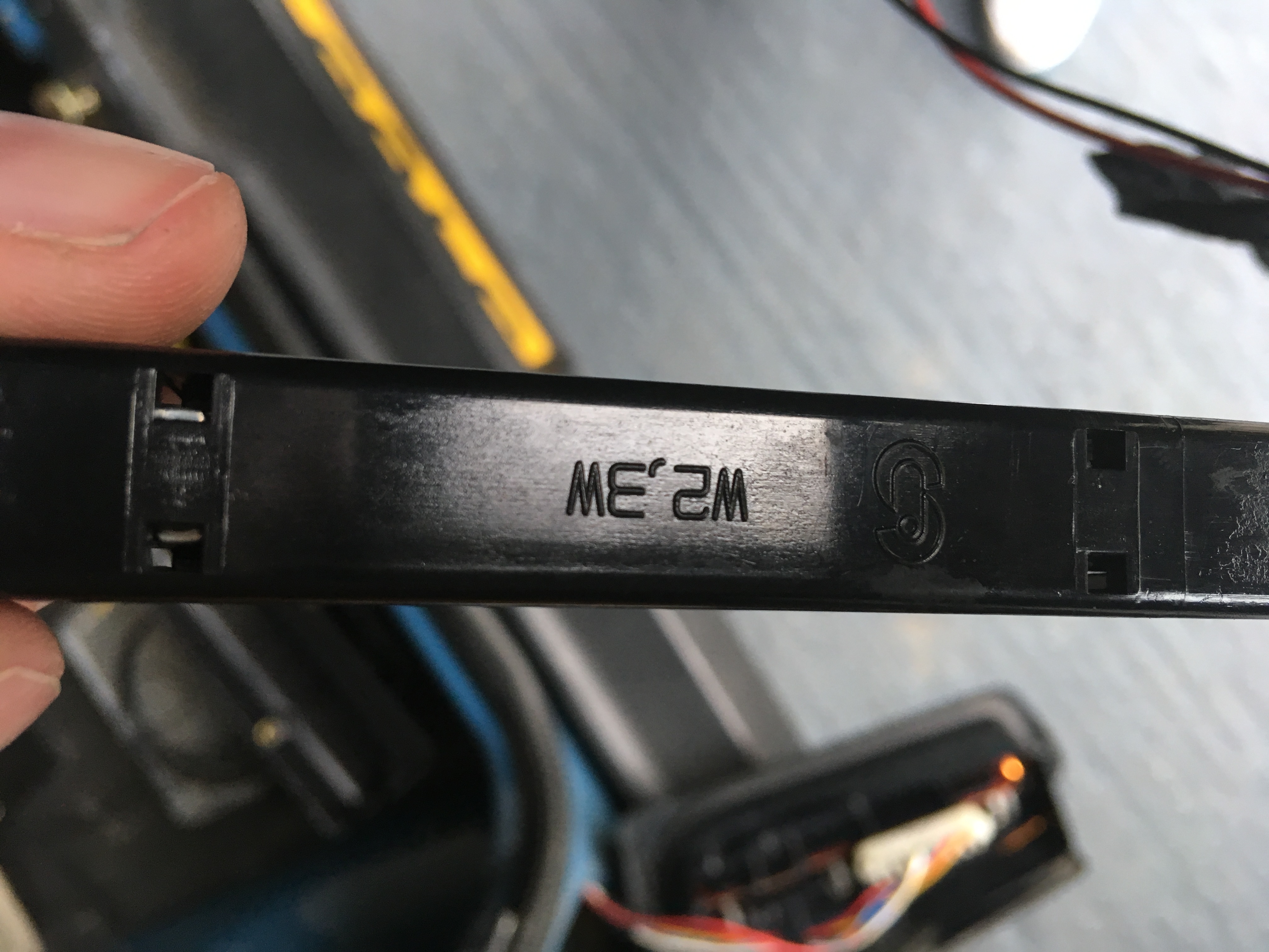
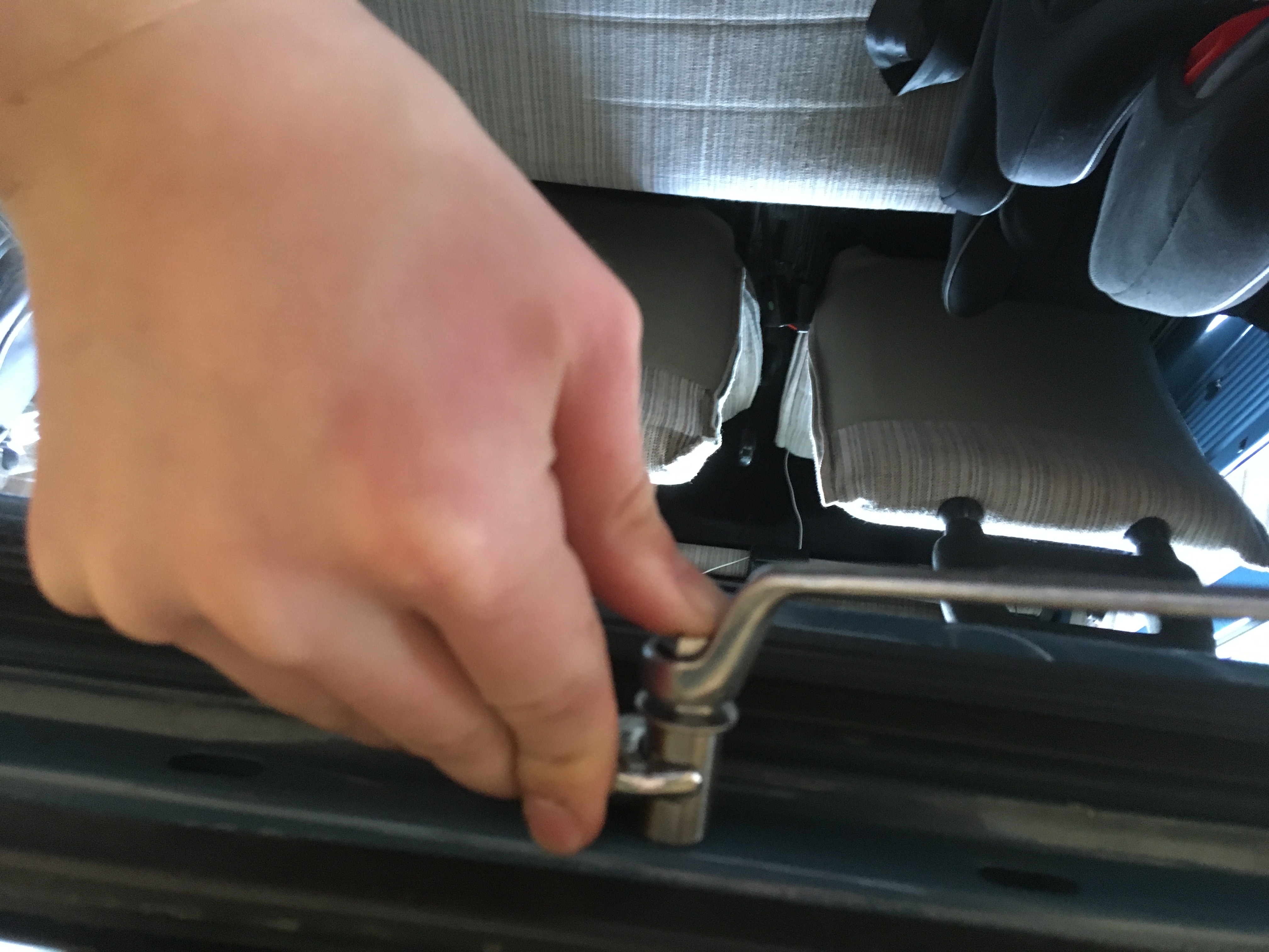
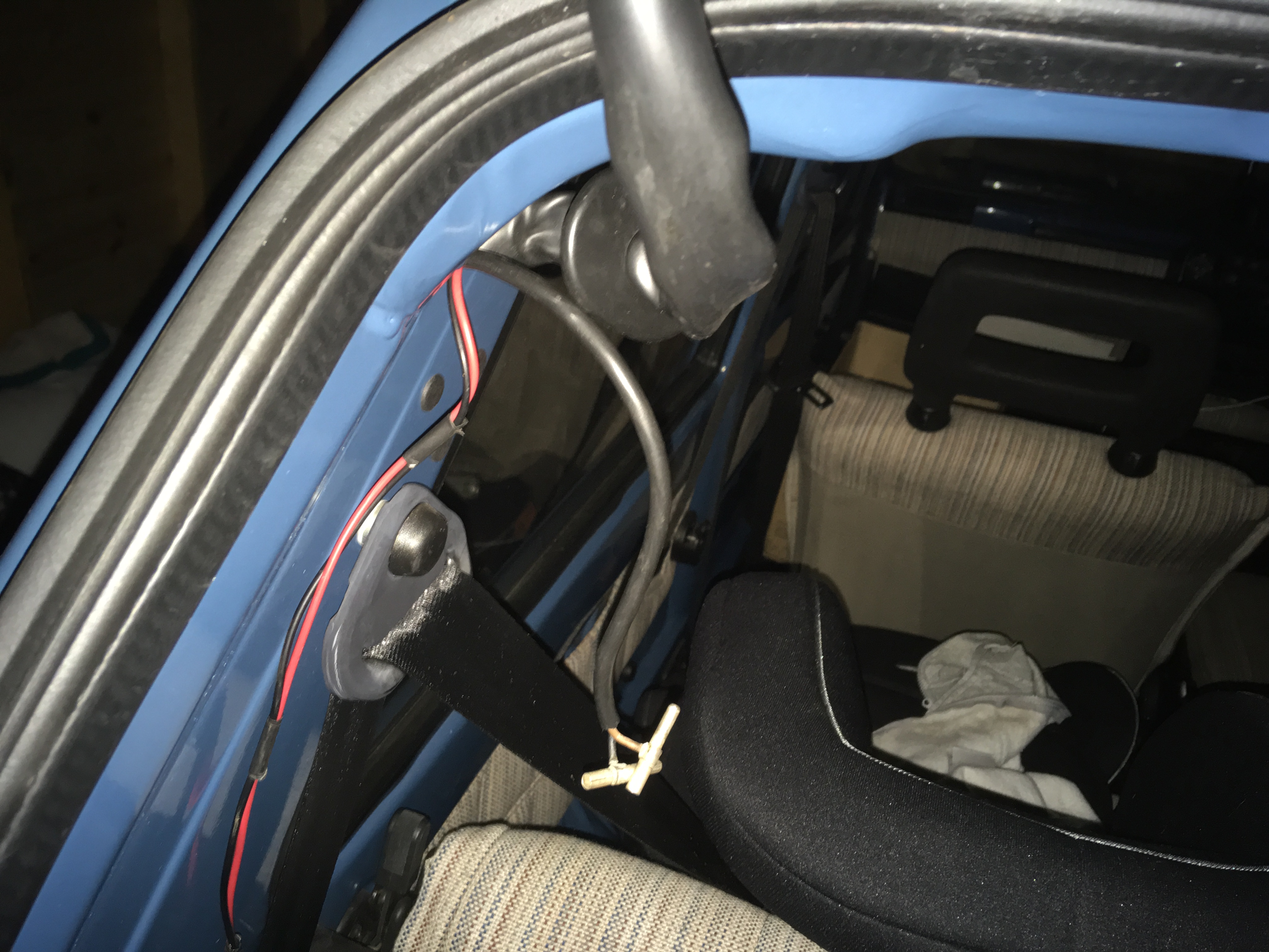
Using Phillips head end of screwdriver, remove the left hand brake cluster (right is possible too, but for the sake of showing exactly what I did I will show left side) remove the top and bottom screws holding cluster on and remove connector block and negative cable. Note that the red wire (second from top) is the positive feed for when brake pedal is pressed, test with a voltage meter on pressing the pedal to be sure as some changes may apply between models. You should get a 12v current when the brake pedal is pressed. To check that the third brake light is functional before you go any further, strip the cable ends that come attached to it, hold the black to the negative feed and the positive to the positive feed metal strip behind the bulb, or indeed the connector block itself. It will light up when the brake pedal is pressed.
Step 2 -
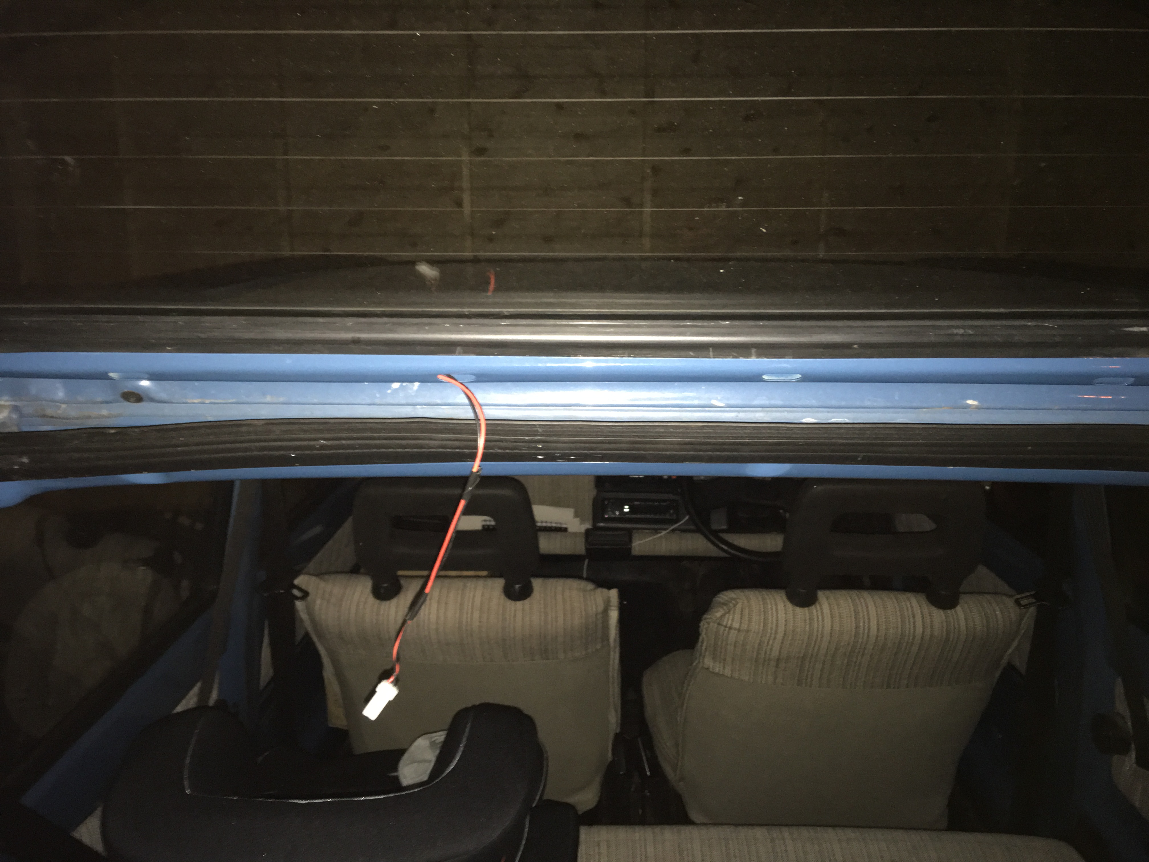
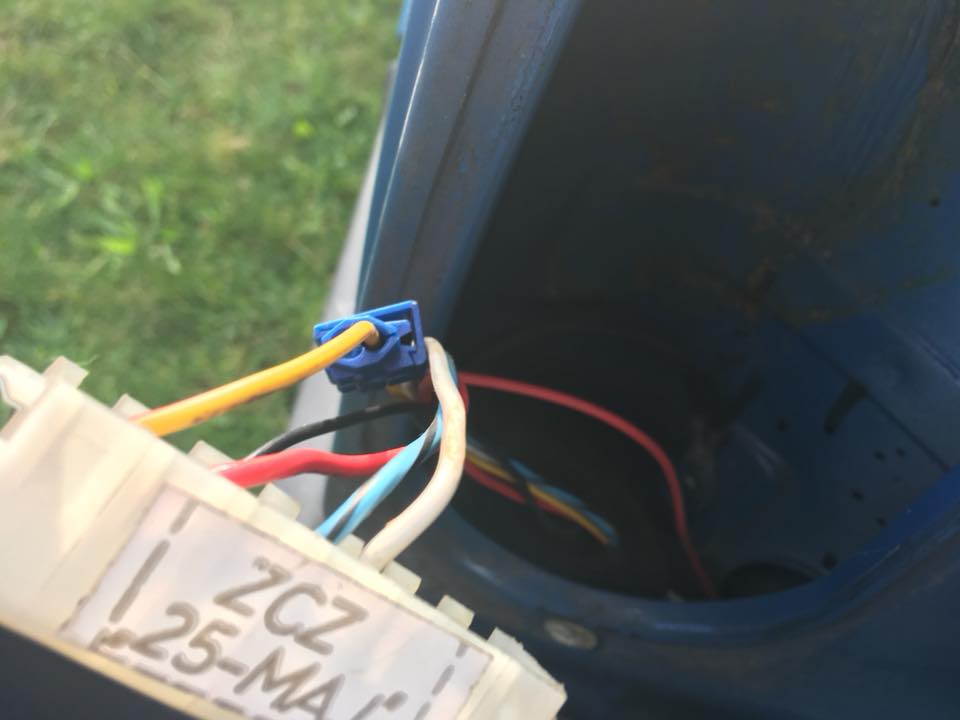
Having Confirmed the positive and negative feeds, turn your attention to the third brake light. Assuming that you have the white connector block and a red and black wire coming from it, strip back the plastic from the ends of each cable. (if you havent already done this to test it) Using the 5 amp red cable, measure roughly how much you will need and add on some in case of error. You need the cable to be fed through the existing hole in the tailgate, along to the rubber sleeve which holds the rear window heating wire. Down the Rubber sleeve and into the car bodywork cavity. From there it must be fed to the rear cluster exit. I did this by insulating taping the new red and black wires together at 4 inch intervals along the length of it, feeding it through the rubber sleeve as directed here, and then tieing a larger thicker piece of wire to it, and feeding the larger thicker wire through the bodywork as it is easier to direct to the exit. then simply untie the larger wire (again, other methods are available) and tape the free ends of the new cable to the bodywork so they do not slip back into the aperture.
Step 3-
You should have 2 ends of each cable at each side of its length visible. Strip all 4 ends. At the third brake light end, attach the positive cable to the positive new cable. This can be done in a variety of ways, but for the purpose of tidyness and ease I crimped the 2 ends together and inserted them into the bodywork. Repeat this process for the Negative cables. Now test the connection again as described in step 1 to make sure the connection is stable at the third brake light end.
Step 4-
Using the wire cutters, sever the brake cluster positive and negative cables and strip both ends. (alternatively you can crimp a ring connection onto the third brake light negative and use the body earth point here, making sure to grease the connection with copper grease, other conductive pastes are available as always)connect the 3 positive wire ends together now using the connector block/insulating tape/scotchlok of your choice. Repeat the process with the 3 negative wire ends. (or ignore if you chose to use the body earth point)
Step 5-
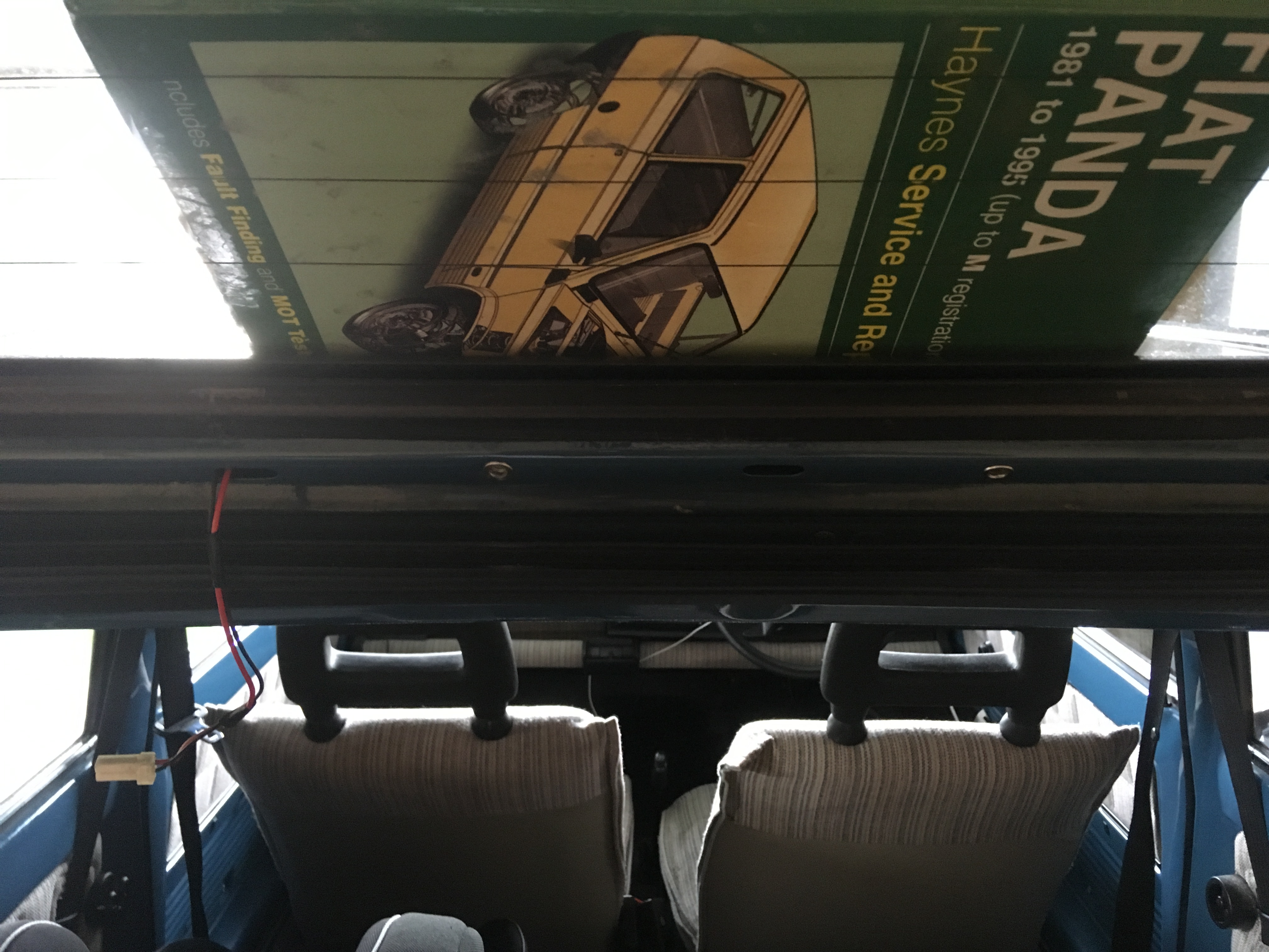
Test the third brake light activates when the brake pedal is pressed once again. Assuming it does then your connections are all fine and the third brake light can be disconnected for now and placed to the side. Replace the left hand brake cluster. Fitting is the reverse of removal as all the best books say.
Step 6-
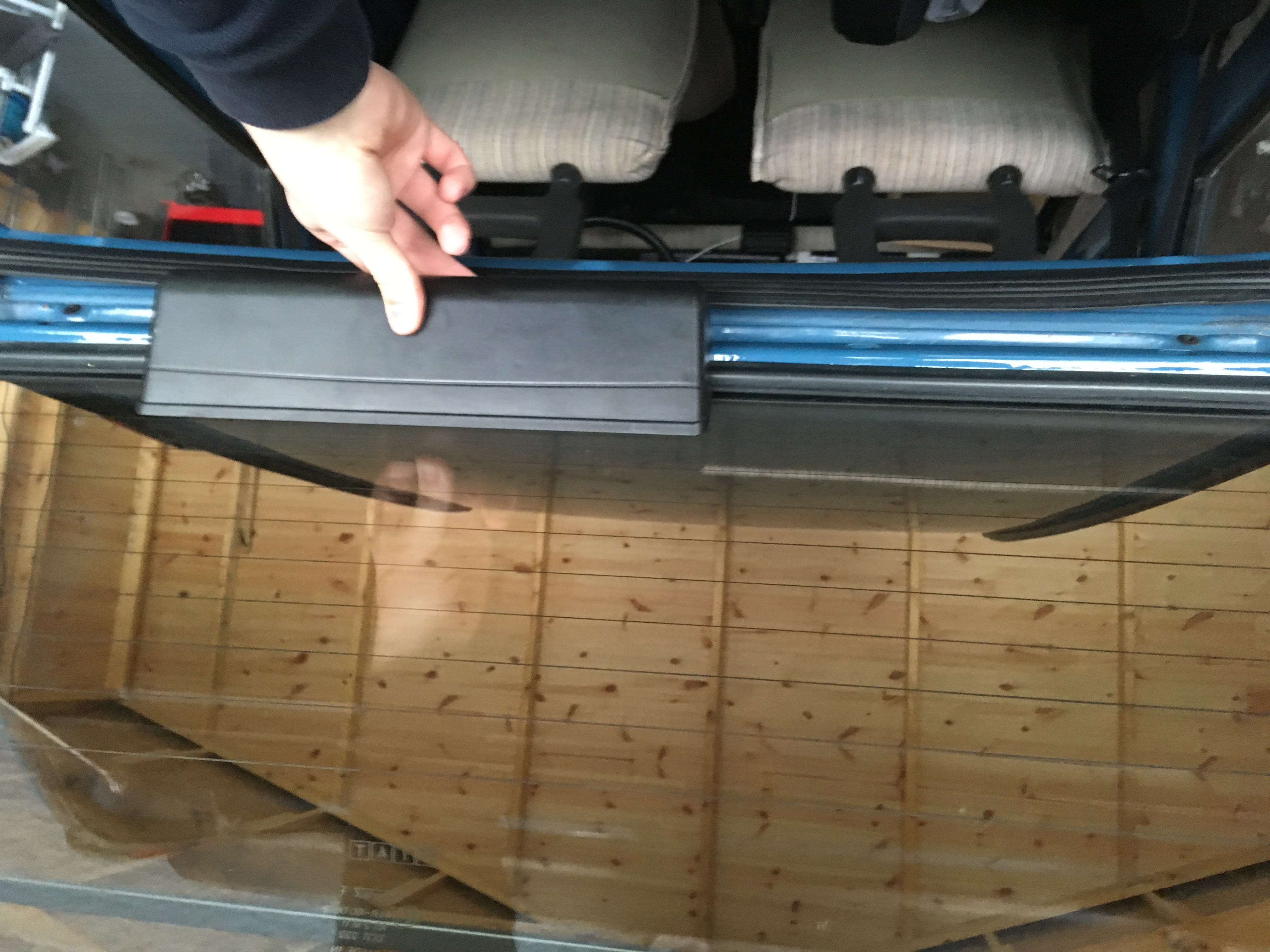
From Corner to Corner the rear window edge is 90cm. The brake light unit is 34 cms long. This means that there will be 28cms between the edge of the brake light unit and the corner of the rear window edge. Masking tape the painted portion of tailgate here. With this in mind measure 28 cms either side of it and hold it in place. Verify that it looks in position, and measure twice. The curves of the unit fit snugly where the rubber and tailgate curves are so make sure it is properly located on both sides. Using a thin marker pen, or similar, poke through the screw holes in the unit and mark the tailgate masking tape through them. Remove the light unit. You will now have 2 position markers for holes. Verify and re-verify till you are happy you have the correct position. Measure twice drill once!
Step 7-
I used an M6 Drill Bit and then bored out to M8, but it comes to the same thing, I was playing safe. Drill the holes one at a time, take your time too as you dont want to damage or dent the metal by leaning too hard. Once you have the first hole drilled, recheck the fitment of the brake light unit to verify the holes will indeed line up with the screws.
Step 8-
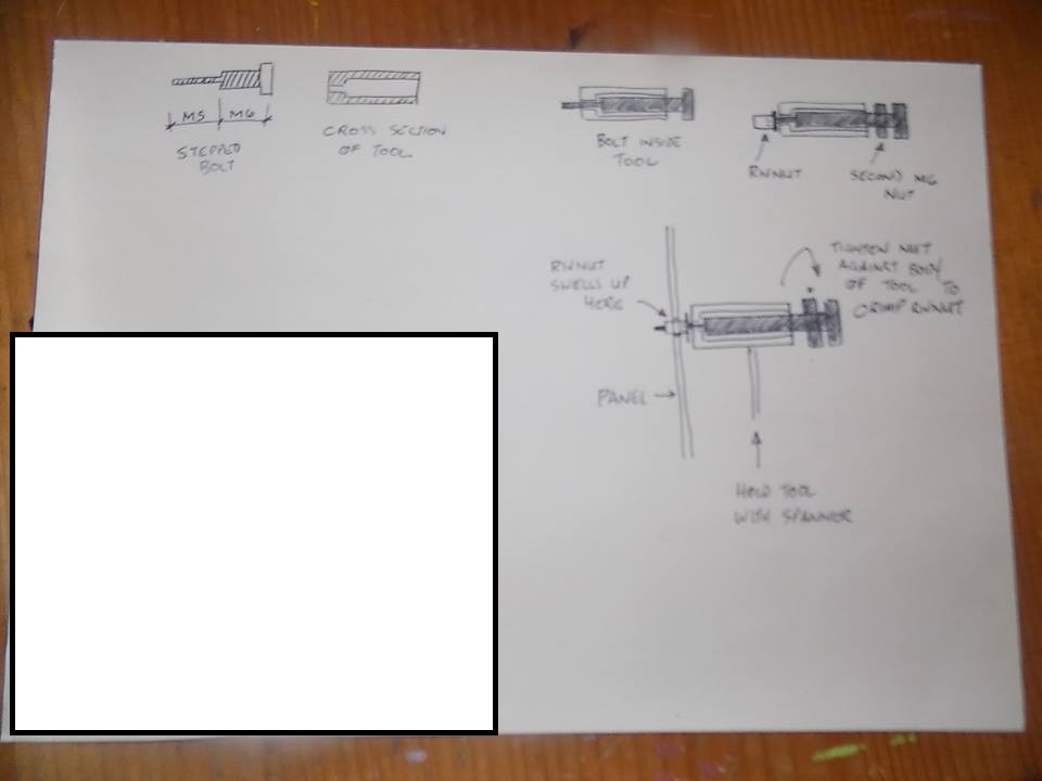
Now that you have the holes you will want to use your M5 Rivnut tool (I used a spanner use one, but there are more expensive versions on the market which function differently. As long as the rivnut gets crushed on the inside of the tailgate its fine). To use it, simply take one of the rivets and thread it onto the tool. Insert it into the cavity. Using a 13mm spanner, grip the barrel of the tool and place the spanner to the inside edge where the tailgate rubber helps to keep it still. Using another 13mm spanner (I used a swan neck but I imagine an open face will be just as good, a ratchet one would be perfect) tighten the nut towards the barrel of the tool and use your thumb to press against the tool against the panel. Do this until you are happy that the tool will have pulled the rivnut up and crushed it inside the panel. Once you have done this, loosen the bolt of the tool while still the barrel is still held by the other 13mm spanner. This withdraws the tool leaving you a rivnut held in place
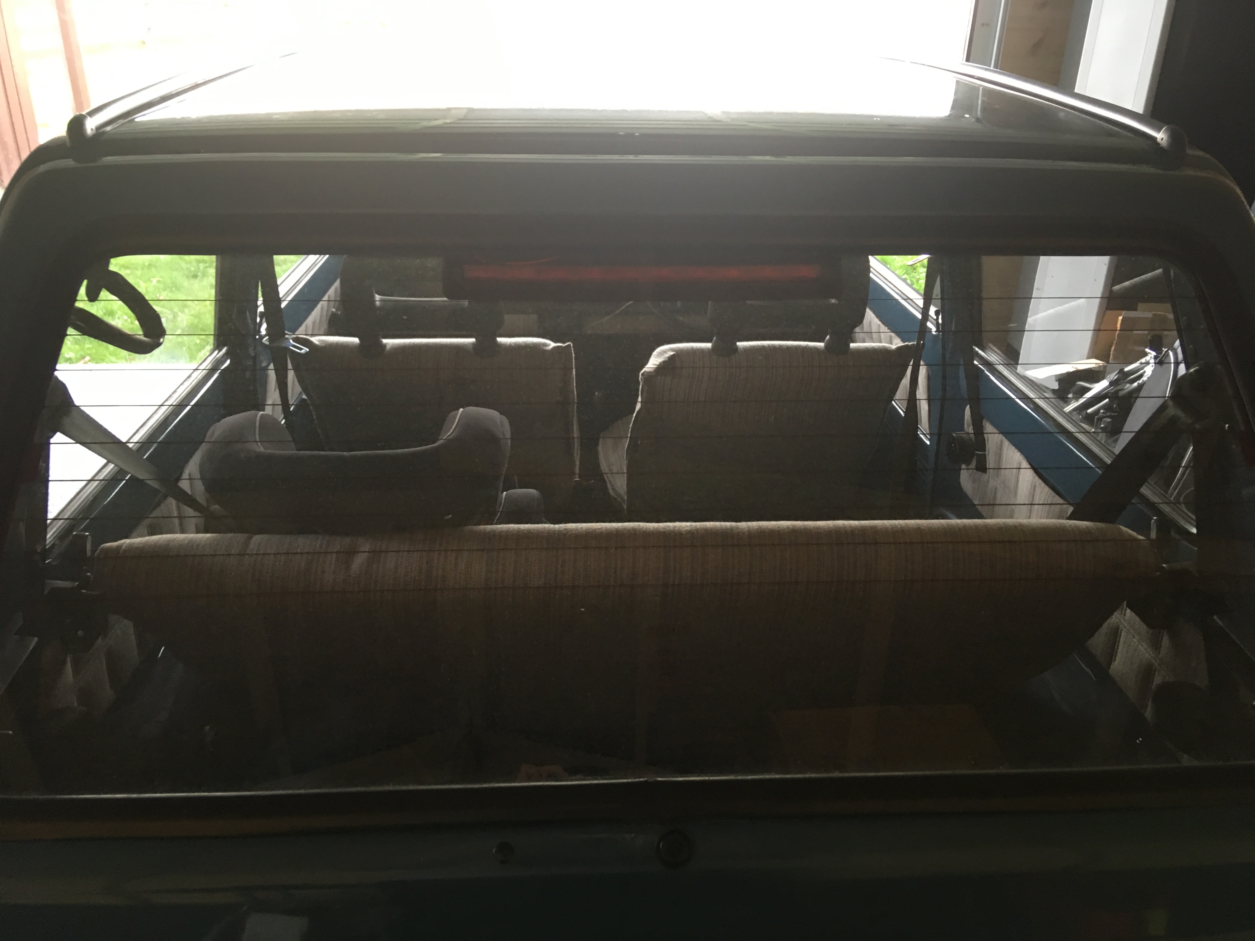
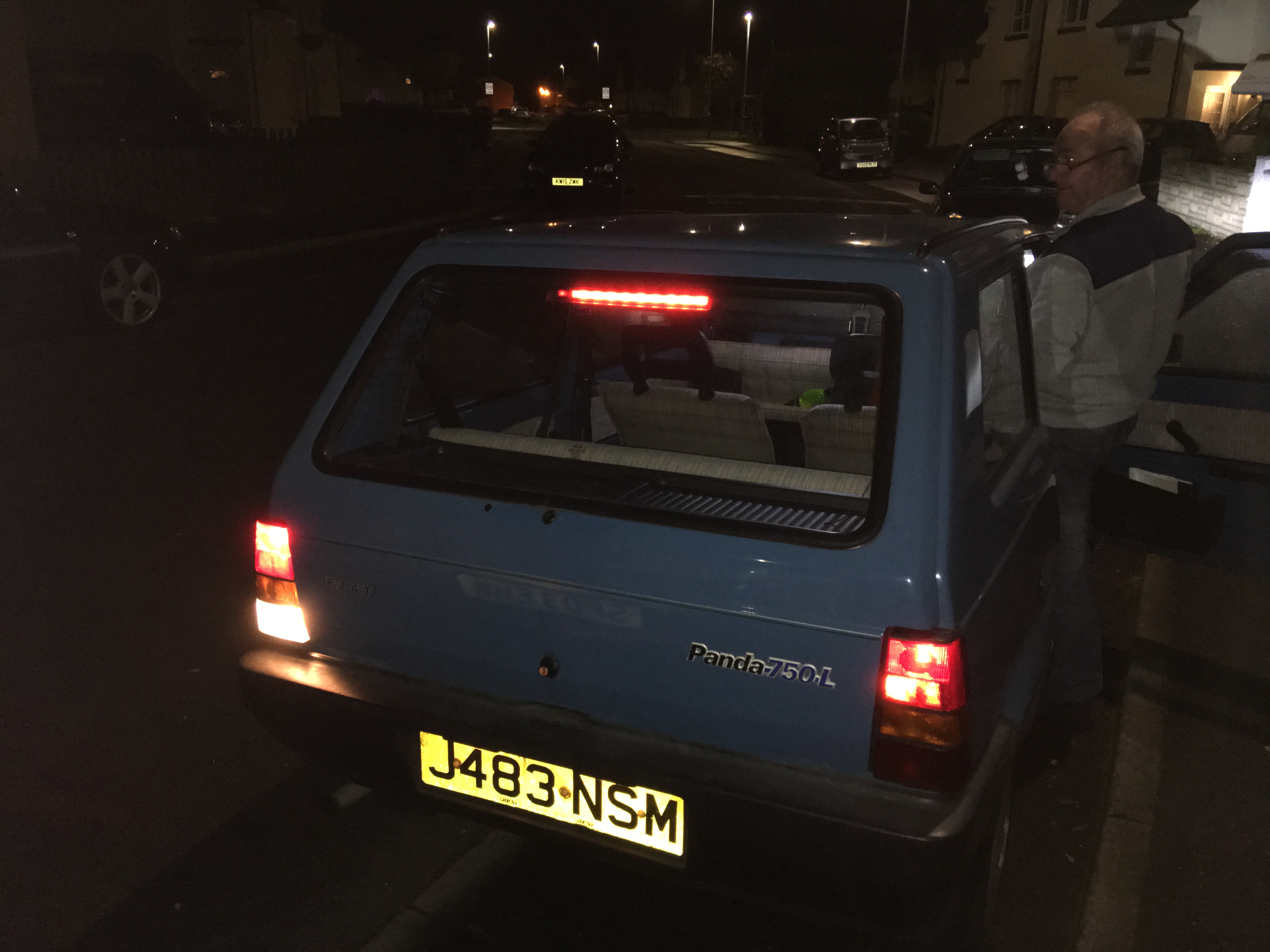
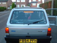
Step 9-
Reconnect the connector block and third brake light, feed the wire through the tailgate to conceal it as much as possible, but dont worry if some ends up in the unit. It can always be moved later. Using the size 4 allen key, or allen key bit in a screwdriver like I did, tighten the screws in until the unit sits flush and you are happy it will not rattle under movement. Check it is all working, and job done.
I hope this helps someone, I had a lot of help planning it out, and this guide is because I had that help. I am sure there are places where my methods could be further improved, but I am happy this is a functional guide.
Parts Required:
1 x Third Brake Light - 165559760 (NOT AVAILABLE FROM FIAT, SOURCE FROM BREAKING CAR ABROAD. FRENCH EBAY SEARCH TERM IS "FEU STOP" AND ITALIAN SEARCH TERM IS "TERZA LUCE" PRECEDED BY FIAT PANDA IN BOTH CASES. ASK FOR AS MUCH WIRING FROM THE CAR AS THEY ARE WILLING TO GIVE YOU, THE CONNECTOR AND THE POSITIVE AND NEGATIVE ARE VERY HELPFUL.
2 x Screws Part No - 46451281
2 x Rivnuts Part No - 15624311 (M5 x 14)
2 x Wire Connector Blocks of Choice
10 x Bulbs Part Number- 71713092 (2.3w wedge type, though LED equivalents are available)
5 Amp Cable Red - Halfords HEF 711
5 Amp Cable Black - Halfords HEF 712
Insulating Tape, also at Halfords and other car electrical suppliers
Optional Parts if Wiring not included-
Connection 2 Vie Poster Part No - 12484680 <white connector block which goes into light unit)
Terminal 1 - 12483444
Terminal 2 - 12319744
Tools Required-
M5 Rivnut Tool
Voltage Meter
M8 Metal Drill Bit
Drill (Cordless with Plenty Charge preferred as more room without cord)
Flathead Screwdriver/Phillips head screwdriver (Supplied Toolkit one is ace)
Wire Stripping and crimping tool
2 x 13mm spanner, open face for body of tool and swan neck (or open face) for tightening nut
Allen Key size 4
Measuring tape
Haynes Manual (To block light coming through rear window obscuring the work area haha)
Step 1 -
Using Phillips head end of screwdriver, remove the left hand brake cluster (right is possible too, but for the sake of showing exactly what I did I will show left side) remove the top and bottom screws holding cluster on and remove connector block and negative cable. Note that the red wire (second from top) is the positive feed for when brake pedal is pressed, test with a voltage meter on pressing the pedal to be sure as some changes may apply between models. You should get a 12v current when the brake pedal is pressed. To check that the third brake light is functional before you go any further, strip the cable ends that come attached to it, hold the black to the negative feed and the positive to the positive feed metal strip behind the bulb, or indeed the connector block itself. It will light up when the brake pedal is pressed.
Step 2 -
Having Confirmed the positive and negative feeds, turn your attention to the third brake light. Assuming that you have the white connector block and a red and black wire coming from it, strip back the plastic from the ends of each cable. (if you havent already done this to test it) Using the 5 amp red cable, measure roughly how much you will need and add on some in case of error. You need the cable to be fed through the existing hole in the tailgate, along to the rubber sleeve which holds the rear window heating wire. Down the Rubber sleeve and into the car bodywork cavity. From there it must be fed to the rear cluster exit. I did this by insulating taping the new red and black wires together at 4 inch intervals along the length of it, feeding it through the rubber sleeve as directed here, and then tieing a larger thicker piece of wire to it, and feeding the larger thicker wire through the bodywork as it is easier to direct to the exit. then simply untie the larger wire (again, other methods are available) and tape the free ends of the new cable to the bodywork so they do not slip back into the aperture.
Step 3-
You should have 2 ends of each cable at each side of its length visible. Strip all 4 ends. At the third brake light end, attach the positive cable to the positive new cable. This can be done in a variety of ways, but for the purpose of tidyness and ease I crimped the 2 ends together and inserted them into the bodywork. Repeat this process for the Negative cables. Now test the connection again as described in step 1 to make sure the connection is stable at the third brake light end.
Step 4-
Using the wire cutters, sever the brake cluster positive and negative cables and strip both ends. (alternatively you can crimp a ring connection onto the third brake light negative and use the body earth point here, making sure to grease the connection with copper grease, other conductive pastes are available as always)connect the 3 positive wire ends together now using the connector block/insulating tape/scotchlok of your choice. Repeat the process with the 3 negative wire ends. (or ignore if you chose to use the body earth point)
Step 5-
Test the third brake light activates when the brake pedal is pressed once again. Assuming it does then your connections are all fine and the third brake light can be disconnected for now and placed to the side. Replace the left hand brake cluster. Fitting is the reverse of removal as all the best books say.
Step 6-
From Corner to Corner the rear window edge is 90cm. The brake light unit is 34 cms long. This means that there will be 28cms between the edge of the brake light unit and the corner of the rear window edge. Masking tape the painted portion of tailgate here. With this in mind measure 28 cms either side of it and hold it in place. Verify that it looks in position, and measure twice. The curves of the unit fit snugly where the rubber and tailgate curves are so make sure it is properly located on both sides. Using a thin marker pen, or similar, poke through the screw holes in the unit and mark the tailgate masking tape through them. Remove the light unit. You will now have 2 position markers for holes. Verify and re-verify till you are happy you have the correct position. Measure twice drill once!
Step 7-
I used an M6 Drill Bit and then bored out to M8, but it comes to the same thing, I was playing safe. Drill the holes one at a time, take your time too as you dont want to damage or dent the metal by leaning too hard. Once you have the first hole drilled, recheck the fitment of the brake light unit to verify the holes will indeed line up with the screws.
Step 8-
Now that you have the holes you will want to use your M5 Rivnut tool (I used a spanner use one, but there are more expensive versions on the market which function differently. As long as the rivnut gets crushed on the inside of the tailgate its fine). To use it, simply take one of the rivets and thread it onto the tool. Insert it into the cavity. Using a 13mm spanner, grip the barrel of the tool and place the spanner to the inside edge where the tailgate rubber helps to keep it still. Using another 13mm spanner (I used a swan neck but I imagine an open face will be just as good, a ratchet one would be perfect) tighten the nut towards the barrel of the tool and use your thumb to press against the tool against the panel. Do this until you are happy that the tool will have pulled the rivnut up and crushed it inside the panel. Once you have done this, loosen the bolt of the tool while still the barrel is still held by the other 13mm spanner. This withdraws the tool leaving you a rivnut held in place
Step 9-
Reconnect the connector block and third brake light, feed the wire through the tailgate to conceal it as much as possible, but dont worry if some ends up in the unit. It can always be moved later. Using the size 4 allen key, or allen key bit in a screwdriver like I did, tighten the screws in until the unit sits flush and you are happy it will not rattle under movement. Check it is all working, and job done.
I hope this helps someone, I had a lot of help planning it out, and this guide is because I had that help. I am sure there are places where my methods could be further improved, but I am happy this is a functional guide.