Early Talbot Express and Fiat Ducato Semi Air Suspension Installation
 There's several systems on the market, most are the same as each other, but with different price tags.
FirestoneTM is the biggest producer of air assisted systems who market theirs as Drive-RiteTM. They are the same system/components as AirideTM.
These systems are well designed for most people to fit themselves as no special tools are required.
The vehicle below is an early Fiat Ducato (similar chassis to a Talbot Express) which is being fitted with a Firestone Drive-Rite Kit.
Most of the small components are packed in a polythene bag. The bag contains all the necessary air fittings, nuts, bolts and cable ties to clip the hose up tidily.
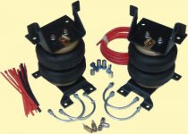
I've loosely assembled the units to create the following photo, so that you get an idea of how its assembled without the vehicle parts blocking the view.
There are several ways to fit these units to the vehicle. I found the easiest way is to reverse the vehicle up on to some car ramps which raise the vehicle by about a foot, this gives ample space to work under the vehicle. DO MAKE SURE the handbrake is on, its in reverse gear and the wheels are chocked before going under your vehicle.
Another way to fit the units, is to jack up the vehicle and support on suitable jack stands, then remove the wheels, but I feel this all takes time and you'll end up crawling under your vehicle to clip the pipes, so why not do it in one go?
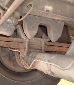
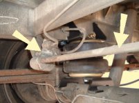
This photo (viewed from behind the axle, looking at the nearside wheel) shows the air spring in position. If the gap between the axle and the chassis is too small, you can use a scissor jack between the chassis and the leaf spring to widen the gap. I took the easy route and used a high lift jack on the tow bar to lift the bodywork up, thus giving more room where I wanted it.
Once in position, you need to tighten the bolts in the nutserts as shown below. I used a combination spanner to steadily tighten mine up. It will be stiff for quite a while, be patient, then it will eventually get tight. Don't forget to do the one the other side the air spring!
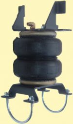
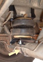
With the top mountings now secure, use the large 'U' bolts to secure the bottom of the air spring to the axle casing. On this vehicle I found the one brake pipe was in a position that was likely to rub on the 'U' bolt, so using some of the sleeving supplied with the kit I used it on the 'U' bolt to help protect the brake pipe as shown by the arrow below. Its not very clear on the photo below, but there is quite a large gap between the axle tube and the U bolt, unless your fully confident of your skills and the gaps, fit the U bolt between the brake pipe and the axle tube.
The hose connections are real simple to use, providing you have cut the hose reasonably square, you simply push the hose in to the fitting until it stops. To release, you have to push the coloured ring in to the fitting, then pull the hose out. They do seal extremely well, though if they do leak slightly, increasing the air pressure for a week or so usually does the trick. I have found installations carried out in cold weather are more prone to leaking as the pipes are hard and don't bed in so well. As mentioned earlier, raising the pressure for a while will help.
I normally add a loop of hose to aid working on the gauge assembly, but as this isn't such a tight installation, I felt there was no need.
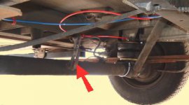
(View from front of vehicle, towards the rear axle)
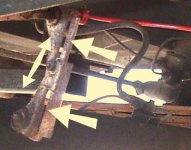
(This photo is a close up of what's pointed out in the photo above)
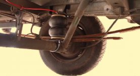
The top photo is with the air springs inflated, also notice the bow in the leaf spring and the gap between the upper and lower leaves.
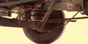
This photo shows the air spring deflated. The leaf spring in this case is almost flat, infact when loaded it is flat and there is no gap between the upper and lower leaves.
FirestoneTM is the biggest producer of air assisted systems who market theirs as Drive-RiteTM. They are the same system/components as AirideTM.
These systems are well designed for most people to fit themselves as no special tools are required.
The vehicle below is an early Fiat Ducato (similar chassis to a Talbot Express) which is being fitted with a Firestone Drive-Rite Kit.
For this job the following components are supplied by Firestone (partially assembled).
Most of the small components are packed in a polythene bag. The bag contains all the necessary air fittings, nuts, bolts and cable ties to clip the hose up tidily.
I've loosely assembled the units to create the following photo, so that you get an idea of how its assembled without the vehicle parts blocking the view.
There are several ways to fit these units to the vehicle. I found the easiest way is to reverse the vehicle up on to some car ramps which raise the vehicle by about a foot, this gives ample space to work under the vehicle. DO MAKE SURE the handbrake is on, its in reverse gear and the wheels are chocked before going under your vehicle.
Another way to fit the units, is to jack up the vehicle and support on suitable jack stands, then remove the wheels, but I feel this all takes time and you'll end up crawling under your vehicle to clip the pipes, so why not do it in one go?
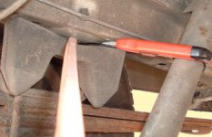
To start mounting the units on the vehicle, this is achieved by removing the bump stops, shown below.
The above bump stop can easily be removed by using a big bendy screwdriver and craft knife. Yes its a one way process, but I've never been able to remove one intact.
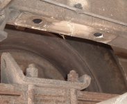
After removing the bump stop you should have the same as below
Using your bendy screwdriver, poke it up into the holes to remove the remains of the bump stops. Don't worry about trying to retrieve them as they will be difficult to retrieve and won't do any damage/harm
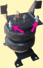
Before progressing any further, you'll need to assemble the brackets and air fitting on to the air spring as shown below. Except the two items with the arrows, make sure you tighten all the nuts etc. as you won't be touching them again. The two items arrowed should only be assembled finger tight. These have a variety of names like 'nutserts' 'nutrivs', call them what you like, but what they do when you tighten the bolts is start to collapse and the sides bulge out like a blind pop rivet. Using these nutserts, enables you to fix the top bracket to the chassis without any drilling, by using the holes that were used by the bump stops. Before fitting the assembly below into position, I like to coat the outside of the nutserts with some heavy duty thread locking compound (Loctite 638 in my case), so that when the nutserts are collapsed they are held more securely with the locking compound.
Before progressing any further, you'll need to assemble the brackets and air fitting on to the air spring as shown below. Except the two items with the arrows, make sure you tighten all the nuts etc. as you won't be touching them again. The two items arrowed should only be assembled finger tight. These have a variety of names like 'nutserts' 'nutrivs', call them what you like, but what they do when you tighten the bolts is start to collapse and the sides bulge out like a blind pop rivet. Using these nutserts, enables you to fix the top bracket to the chassis without any drilling, by using the holes that were used by the bump stops. Before fitting the assembly below into position, I like to coat the outside of the nutserts with some heavy duty thread locking compound (Loctite 638 in my case), so that when the nutserts are collapsed they are held more securely with the locking compound.
EXTRA INFO - Before offering the bracket up to the chassis for final fixing, its best to see how far the nutsert (on it's own) will go into the chassis as some holes are recessed more than others. If the nutsert is not flush with the chassis surface, and is recessed, it's best to use some serrated washers between the bracket and the nutsert. The serrated washers will help prevent the nutsert turning when you start to tighten the fixing bolt, and hold the nutsert high enough to prevent the nutsert collapsing below the chassis and falling out. Even if the nutsert is flush with the chassis, I recommend using a serrated washer to help prevent the nutsert turning. After the nutserts have been set in the chassis, remove the serrated washers.
This photo (viewed from behind the axle, looking at the nearside wheel) shows the air spring in position. If the gap between the axle and the chassis is too small, you can use a scissor jack between the chassis and the leaf spring to widen the gap. I took the easy route and used a high lift jack on the tow bar to lift the bodywork up, thus giving more room where I wanted it.
Once in position, you need to tighten the bolts in the nutserts as shown below. I used a combination spanner to steadily tighten mine up. It will be stiff for quite a while, be patient, then it will eventually get tight. Don't forget to do the one the other side the air spring!
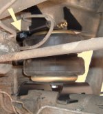
With the top mountings now secure, use the large 'U' bolts to secure the bottom of the air spring to the axle casing. On this vehicle I found the one brake pipe was in a position that was likely to rub on the 'U' bolt, so using some of the sleeving supplied with the kit I used it on the 'U' bolt to help protect the brake pipe as shown by the arrow below. Its not very clear on the photo below, but there is quite a large gap between the axle tube and the U bolt, unless your fully confident of your skills and the gaps, fit the U bolt between the brake pipe and the axle tube.
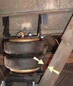
Something to be aware of, and that is to make sure the bracket on the axle is parallel with the top bracket to avoid misalignment of the air spring. Whilst your aiming to keep the brackets parallel with one another, do check the gap between the air spring and the shock absorber shown below, as you don't want the air spring resting on the shock absorber (also check when inflated to maximum pressure) as it will eventually wear a hole in the air spring.
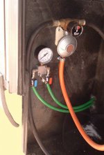
Once both air springs have been installed, you need to decide where to install your optional extra gauge and valves, or at least where to fit the compressed air filling point. Most people like them installed in the cab, however on this vehicle the owner wanted them in with the gas bottles as shown below.
The gauge and valve assembly comes in several formats of hose connections. If installing in the foot well of the cab, its best to have the hoses coming in to the assembly from the side, however in the above its best for vertical connections. The colour coding of the hoses and valves I use, is with red on the left as all the markers on the left of the road are also red, so that leaves blue on the right. Yep the above looks opposite to my description, however the photo was taken looking towards the back of the vehicle. Where ever the hoses pass through any holes or possibly likely to be rubbed, I always use some out sleeving (large sized hose in this case) to help protect the inner hose.
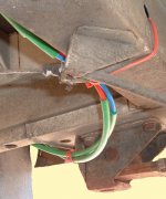
The hose connections are real simple to use, providing you have cut the hose reasonably square, you simply push the hose in to the fitting until it stops. To release, you have to push the coloured ring in to the fitting, then pull the hose out. They do seal extremely well, though if they do leak slightly, increasing the air pressure for a week or so usually does the trick. I have found installations carried out in cold weather are more prone to leaking as the pipes are hard and don't bed in so well. As mentioned earlier, raising the pressure for a while will help.
I normally add a loop of hose to aid working on the gauge assembly, but as this isn't such a tight installation, I felt there was no need.
There's no need to start drilling holes everywhere (apart from where the hoses went through the back of the gas locker box) to use the cable ties, as you'll find plenty of convenient places to fix to as shown above. Again, personal choice, if the tie is long enough, I like to wrap cable ties round several times to help excessive stress in one place as shown above.
With all the pneumatics finished, the brake load sensing valve (LSV) needs to be checked and adjusted if necessary. The LSV is shown below (left arrow), and actuated by a lever (right arrow)
The LSV is plumbed in to the rear brakes and controls the amount of brake pressure applied to the rear axle. Through levers, it senses the height of the chassis in relation to the axle. With the chassis low, it applies maximum break pressure, but when the chassis is high with no load, it applies minimal pressure. The reason for this is to avoid the rear wheels locking up with no load on the chassis. If this happened going round a corner, you'll end up with a situation like a handbrake turn and find the rear of the vehicle overtaking you. With motorhomes, they are always loaded (you never go home and remove the body, or do you?) so the LSV quite often seizes up. Most MoT testers are switched on enough to realize its not an issue with motorhomes so don't worry about it.
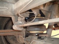
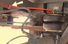
With the semi air suspension lifting the body away from the axle, there is a chance that the LSV thinks there is no load on the rear axle and starts to limit the braking capacity. There are kits available to counteract the LSV getting it wrong, but these are generally only fitted to empty vans or flat bed trucks where the load is removed. To avoid the LSV getting it wrong on a permanently loaded chassis (as with a motorhome), you'll need to alter the LSV linkage. On the rear axle you'll find a slotted/slider adjuster, as pointed out by the red arrow below.

(View from front of vehicle, towards the rear axle)

(This photo is a close up of what's pointed out in the photo above)
If not already done, as was this vehicle, you need to loosen the fixing screws in the middle of the slider, and move the two halves apart as shown above. If your unsure of this, and its effect on the brakes I thoroughly recommend you pump up your suspension to its highest position and have your brakes tested at a MoT station (Not sure, but I don't think there is a charge for this), then at least you'll know whether its set correctly or not.
That completes your installation, and your system is ready to use.
I didn't take any photos of the before and after effect from outside the vehicle, however the two following photos will give an indication of what to expect. The differences are not very great, as the vehicle had empty water tanks etc.
I didn't take any photos of the before and after effect from outside the vehicle, however the two following photos will give an indication of what to expect. The differences are not very great, as the vehicle had empty water tanks etc.

The top photo is with the air springs inflated, also notice the bow in the leaf spring and the gap between the upper and lower leaves.

This photo shows the air spring deflated. The leaf spring in this case is almost flat, infact when loaded it is flat and there is no gap between the upper and lower leaves.
A good starting point for what pressure to inflate your air springs to, try 40psi and experiment up and down from there.
Always have a minimum of 5psi in the air spring when not being used for long periods.
DON'T jack up the body with any pressure above 5psi in your air springs (jacking up the axle will be fine).
DON'T jack up the body with any pressure above 5psi in your air springs (jacking up the axle will be fine).
Disclaimer
The information provided on this Website site is offered with no warranty as to the authenticity, suitability or competence of the individual, company or service quoted here in. This Website shall not be liable for any damage or difficulty, direct or indirect, arising from utilisation of the information contained within these pages.
The information provided on this Website site is offered with no warranty as to the authenticity, suitability or competence of the individual, company or service quoted here in. This Website shall not be liable for any damage or difficulty, direct or indirect, arising from utilisation of the information contained within these pages.


