I thought I would write this guide as me and a few other people have had trouble understanding the instructions that come with the kit.
I've tried to write it as simply as possible, so that people like me (with little electrical knowledge) can hopefully understand.
I'll do it in the 3 steps that it shows in the instructions, but with more detail. Apologies for the bad quality pictures, but i only had my phone.
Click to enlarge
Notes:
You must already have central locking to use this kit!
When looking for a wire in the fuse box, don't go by colour, go by position. When i fitted mine, the only wire that was the colour it was supposed to be was the positive power (red/white).
Time it should take: 30 - 60 minutes.
You will need:
Meta M320 RCL kit (about £100 from Fiat or £30ish on Ebay)
Flat head screw driver
Pliers
5mm Allen Key
A few cable ties
Some electrical Tape
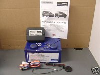
What you get in the kit:
Control unit
A load of wires attatched to a white connector
5x Scotch locks
2x Remotes
2x sticky pads
An LED
Some confusing instructions
The wires you need to connect are:
Red (marked 2 in the instructions)
Red/White (marked 24 in the instructions)
Black (marked 3 in the instructions)
Light Blue/White (marked 39 in the instructions)
Light Blue/Yellow (marked 37 in the instructions)
Red/Yellow (marked 38 in the instructions)
Black (the one that is separate from the rest)
Optional:
Light Blue - For visual confirmation via indicators (marked 14 in the instructions)
White - For flashing LED (Marked 6 in the instructions)
Click to enlarge
Intructions:
Step One
Firstly, to avoid any mishaps - pop the bonnet and disconnect the negative terminal from the battery.

Click to enlarge
You need to access the fuse box to the right of the steering wheel. Use a flat head screw driver to undo the 2 big plastic screws. Open the panel and remove it to give you more room.
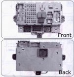
If we look at the instructions provided, you need to access the rear of the fuse box (marked PM on the diagram).You should see 3 allen head bolts holding the fuse box in place. Undo these with a 5mm allen key.
Click to enlarge
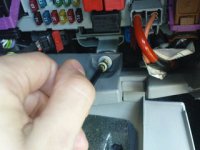
I had abit of trouble getting the fuse box to move, but with a bit of brute force, you should be able to turn it around.
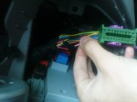
Now that you can access the back of the fuse box - unplug the connector in the top left (PM).
Click to enlarge
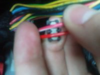
Find the red/white wire coming from this connector and use a scotch lock to connect the red wire (marked 2 in the diagram) from your kit to it. Just put a wire through each side of the bottom part of the scotch lock and push the top part until it clicks into position. I used pliers to do this.
Click to enlarge
Reconnect the connector into PM.
Turn the fuse box back around and trail the red wire underneath.
Don't worry about the other wire it mentions to connect in the first diagram, this is only needed if you are installing an alarm.
Now onto the next part of the instructions.
Step Two

Click to enlarge
Locate the connector marked AH in the diagram, at the right hand side of the fuse box.
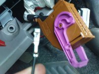
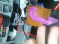
You need to take this connector apart, to enable you to plug the little separate black wire into. Simply push the two little clips in at the side and pull it apart.
If you look closely the connector has little numbers on it. Find number 20 and insert the metal part of your black wire into here.
Click to enlarge
Click to enlarge
Now you need to scotch lock this black wire to your Red/White + Black + Light Blue/White wires. This time, put 2 wires in either side of your scotch lock.
Put the connector back together and reconnect back into AH.
Step Three
Click to enlarge
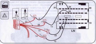
Find connector LN on the bottom left hand corner of the fuse box. Once again, pull this connector apart.
Using the little number, find the wire coming from position 34. Scotch lock it to your Light Blue/Yellow wire.
Find the wire coming from position 24 and scotch lock your Red/Yellow wire to it.
Optional: For indicators to give you visual confirmation when locking/unlocking car. Find the wire coming from position 2 and scotch lock one of your Light Blue wires to it.
Step Four

Click to enlarge
This part is optional, to have a flashing LED, and i chose not to do it as they do not provide enough scotch locks. But I'm sure you can figure this part out yourself if you want to do it
Finishing Up
Plug your white connector into your control unit.
Reconnect the battery. Try it out
Find some where in the fusbox compartment for the control unit to go, and use the sticky pads to hold it in place.
Use cable ties to tidy up the wires, & your done!
I've tried to write it as simply as possible, so that people like me (with little electrical knowledge) can hopefully understand.
I'll do it in the 3 steps that it shows in the instructions, but with more detail. Apologies for the bad quality pictures, but i only had my phone.

Click to enlarge
Notes:
You must already have central locking to use this kit!
When looking for a wire in the fuse box, don't go by colour, go by position. When i fitted mine, the only wire that was the colour it was supposed to be was the positive power (red/white).
Time it should take: 30 - 60 minutes.
You will need:
Meta M320 RCL kit (about £100 from Fiat or £30ish on Ebay)
Flat head screw driver
Pliers
5mm Allen Key
A few cable ties
Some electrical Tape
What you get in the kit:
Control unit
A load of wires attatched to a white connector
5x Scotch locks
2x Remotes
2x sticky pads
An LED
Some confusing instructions
The wires you need to connect are:
Red (marked 2 in the instructions)
Red/White (marked 24 in the instructions)
Black (marked 3 in the instructions)
Light Blue/White (marked 39 in the instructions)
Light Blue/Yellow (marked 37 in the instructions)
Red/Yellow (marked 38 in the instructions)
Black (the one that is separate from the rest)
Optional:
Light Blue - For visual confirmation via indicators (marked 14 in the instructions)
White - For flashing LED (Marked 6 in the instructions)

Click to enlarge
Intructions:
Step One
Firstly, to avoid any mishaps - pop the bonnet and disconnect the negative terminal from the battery.

Click to enlarge
You need to access the fuse box to the right of the steering wheel. Use a flat head screw driver to undo the 2 big plastic screws. Open the panel and remove it to give you more room.
If we look at the instructions provided, you need to access the rear of the fuse box (marked PM on the diagram).You should see 3 allen head bolts holding the fuse box in place. Undo these with a 5mm allen key.

Click to enlarge
I had abit of trouble getting the fuse box to move, but with a bit of brute force, you should be able to turn it around.
Now that you can access the back of the fuse box - unplug the connector in the top left (PM).

Click to enlarge
Find the red/white wire coming from this connector and use a scotch lock to connect the red wire (marked 2 in the diagram) from your kit to it. Just put a wire through each side of the bottom part of the scotch lock and push the top part until it clicks into position. I used pliers to do this.

Click to enlarge
Reconnect the connector into PM.
Turn the fuse box back around and trail the red wire underneath.
Don't worry about the other wire it mentions to connect in the first diagram, this is only needed if you are installing an alarm.
Now onto the next part of the instructions.
Step Two

Click to enlarge
Locate the connector marked AH in the diagram, at the right hand side of the fuse box.
You need to take this connector apart, to enable you to plug the little separate black wire into. Simply push the two little clips in at the side and pull it apart.
If you look closely the connector has little numbers on it. Find number 20 and insert the metal part of your black wire into here.

Click to enlarge

Click to enlarge
Now you need to scotch lock this black wire to your Red/White + Black + Light Blue/White wires. This time, put 2 wires in either side of your scotch lock.
Put the connector back together and reconnect back into AH.
Step Three

Click to enlarge
Find connector LN on the bottom left hand corner of the fuse box. Once again, pull this connector apart.
Using the little number, find the wire coming from position 34. Scotch lock it to your Light Blue/Yellow wire.
Find the wire coming from position 24 and scotch lock your Red/Yellow wire to it.
Optional: For indicators to give you visual confirmation when locking/unlocking car. Find the wire coming from position 2 and scotch lock one of your Light Blue wires to it.
Step Four

Click to enlarge
This part is optional, to have a flashing LED, and i chose not to do it as they do not provide enough scotch locks. But I'm sure you can figure this part out yourself if you want to do it
Finishing Up
Plug your white connector into your control unit.
Reconnect the battery. Try it out
Find some where in the fusbox compartment for the control unit to go, and use the sticky pads to hold it in place.
Use cable ties to tidy up the wires, & your done!

