Fiat Ducato X250 2008 Alternator Replacement
This guide covers DIY replacement of the alternator on a RHD 2008 2.3 Litre Ducato (X250 series) motorhome with air conditioning. Other 2006 onward models will be similar. The original alternator was rated at 140 Amps (504 009 978) and failed during lay-up. Symptoms were battery voltage of 12.5 volts and falling once the engine was running, raised idle speed and battery warning symbol on the dashboard. The replacement I chose (on the basis of same day local availability) was a 30% uprated 180 Amp genuine Fiat part (5801 526 031) and cost £290. A lower rated and/or pattern part would be cheaper of course. You can check which model is originally fitted by taking a picture of the label on the rear face.
Although nothing is intrinsically difficult, the alternator is well hidden down the back of the engine and access is poor. I wouldn’t recommend tackling this job unless you are familiar with spannering ! The job took me 6 hours, but would have been quicker with an assistant to hand the right tools and without stops to figure out the removal process. TBH if I hadn’t needed the van the next day I would have paid someone else to do it. Most access is from below, so get the van raised on ramps by at least 150 mm and lay out something soft to lie on.
You will need:
Several good light sources
Phone camera and/or mirror for recording alternator label and seeing past obstructions
Penetrating oil spray
Torx bit for undertray
13, 15, 16 and 17 mm AF ring, open ended and socket spanners with a good selection of extensions
Torque wrench for 18 and 36 lb.ft
Crowbar/lever to spread exhaust clamp
Tin snips for heat shield
Stout cord for lifting alternator weight
New Fiat alternator or equivalent.
Also possibly new exhaust joint metal sealing ring, new ribbed drive belt if old one is tired.
Disassembly:
Remove negative lead from vehicle battery – quick release clamp
If a motorhome, isolate habitation battery and solar panels etc just to be on the safe side
Remove plastic cover from top of engine, if fitted. One hose clip, 3 pull studs.
Remove plastic under tray from right hand side (15 mm AF and Torx)
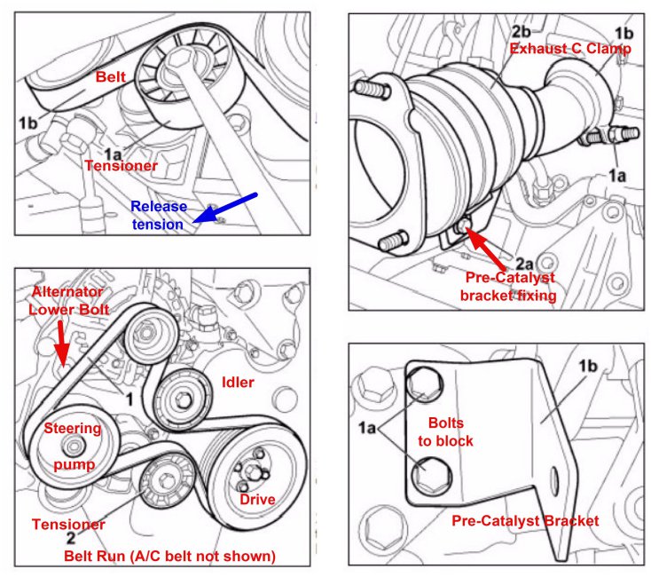
Release the tension from the sprung loaded plain tensioner pulley by turning the centre nut clockwise (13 mm AF). The spring is strong so you need a good length spanner or socket bar. Whilst holding the tension, slip off the 7 ribbed belt and tuck it out of the way. Slowly release the tension. The thinner aircon stretch drive belt (if fitted) can stay put.
From above, remove the 2 pin plastic connector from the alternator, squeeze sides to unlatch
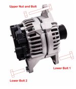
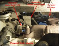
From above, remove the upper nut and bolt securing the alternator (15 mm AF)
Remove the main B+ output cable from the alternator (13 mm AF Nyloc)
Slacken the lower bolt securing the alternator on the side nearest the vehicle centre (17 mm AF)
Remove the second lower alternator bolt. The head is hidden from view, it is immediately above the ribbed power steering pump pulley. The socket length is critical here, too short and the socket bar will foul the pulley, too long and it will foul the chassis. I used a ½ inch to 3/8 inch adaptor to end up with a socket effectively about 65 mm long.
At this point you realise that the alternator is bigger than any extraction route will allow. You have to make more space by loosening the large casting that supports the alternator and power steering pump so that is can be swung to one side a little. You also need to undo the top exhaust clamp and the support bracket so that the pre-catalyst can be pushed to the other side, the flexible joint allows this. No need to disturb the rear joint of the pre-catalyst, which will be rusted up anyway.
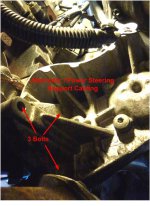
Remove the three bolts (arranged in a triangle) securing the alternator/power steering support casting to the back of the engine block (13 mm AF). Don’t undo the pump itself. This casting is also located by hollow pegs, so needs to be eased away from the block by a few mm before it is free to swing round. No need to disconnect pipes.
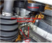
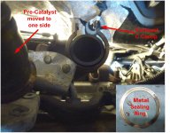
Remove the ‘C’ clamp between pre-catalyst and turbo exhaust outlet (16 mm AF). This is strongly made and will need a good lever or crowbar to spread it enough to slide out of the way. Don’t lose the thin metal sealing ring that sits in this joint, it is held by a circular flange and two tiny pegs on the downpipe but may well drop out as the joint is separated.
Completely remove the exhaust catalyst support bracket, one bolt to the circular band and two bolts holding the bracket to the engine block (13 mm AF). Beware rust in your eyes !
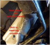
Remove the bolt securing the thin heat shield to the side of the steering column (13 mm AF)
Remove the last (slack) bolt securing the alternator and fiddle the alternator out and down through the gap. If necessary the thin heat shield can be slit with tin snips at its corner to allow it to be temporarily bent out of the way and give a little more wriggle room.
Assembly:
Replacement is the reverse of the above (as Mr Haynes used to say), but here are some top tips:
The alternator is a bit of a beast (7 kg), so unless you are a shot-put champion, tie some cord to the upper fixing hole and get an assistant to take most of the weight from above while you concentrate on fiddling it up and into position. Note that the alternator is bolted into one fixed position, the ribbed belt tension is controlled by the sprung tensioner roller.
The exhaust clamp is strong. I used a long M8 screw and two nuts as a temporary ‘spreader’ to keep it opened up, removing them once it was in place and replacing with the normal nut and bolt.
The output terminal on the 180 Amp alternator was nearer the top than the original, so there wasn’t much slack in the cable when fitted. I also needed some extra packing washers under the eyelet.
Check all electrical connections are clean and bright, treat if necessary.
The alternator lower bolts (2 x M10) should be torqued to 5 daNm (37 lb.ft)
The alternator upper bolt (1 x M8) and the alternator / power steering support casting bolts (3 x M8) should be torqued to 2.5 daNm (18 lb.ft)
The pre-catalyst support bracket (3 x M8) and the exhaust clamp collar (1 x M8) should be torqued to 2.5 daNm (18 lb.ft)
Double check that the ribbed drive belt is properly seated on all the pulleys, and take another look once the engine is running before refitting the undertray. Now would be a good time to replace the ribbed belt if it looks tired. You may have to temporarily take off the thinner aircon stretch belt (if fitted) to allow access.
If all is well, the battery voltage should now be around 14.5 volts with the engine running, idle will be normal 800 RPM and the battery warning light will be extinguished.
This guide covers DIY replacement of the alternator on a RHD 2008 2.3 Litre Ducato (X250 series) motorhome with air conditioning. Other 2006 onward models will be similar. The original alternator was rated at 140 Amps (504 009 978) and failed during lay-up. Symptoms were battery voltage of 12.5 volts and falling once the engine was running, raised idle speed and battery warning symbol on the dashboard. The replacement I chose (on the basis of same day local availability) was a 30% uprated 180 Amp genuine Fiat part (5801 526 031) and cost £290. A lower rated and/or pattern part would be cheaper of course. You can check which model is originally fitted by taking a picture of the label on the rear face.
Although nothing is intrinsically difficult, the alternator is well hidden down the back of the engine and access is poor. I wouldn’t recommend tackling this job unless you are familiar with spannering ! The job took me 6 hours, but would have been quicker with an assistant to hand the right tools and without stops to figure out the removal process. TBH if I hadn’t needed the van the next day I would have paid someone else to do it. Most access is from below, so get the van raised on ramps by at least 150 mm and lay out something soft to lie on.
You will need:
Several good light sources
Phone camera and/or mirror for recording alternator label and seeing past obstructions
Penetrating oil spray
Torx bit for undertray
13, 15, 16 and 17 mm AF ring, open ended and socket spanners with a good selection of extensions
Torque wrench for 18 and 36 lb.ft
Crowbar/lever to spread exhaust clamp
Tin snips for heat shield
Stout cord for lifting alternator weight
New Fiat alternator or equivalent.
Also possibly new exhaust joint metal sealing ring, new ribbed drive belt if old one is tired.
Disassembly:
Remove negative lead from vehicle battery – quick release clamp
If a motorhome, isolate habitation battery and solar panels etc just to be on the safe side
Remove plastic cover from top of engine, if fitted. One hose clip, 3 pull studs.
Remove plastic under tray from right hand side (15 mm AF and Torx)
Release the tension from the sprung loaded plain tensioner pulley by turning the centre nut clockwise (13 mm AF). The spring is strong so you need a good length spanner or socket bar. Whilst holding the tension, slip off the 7 ribbed belt and tuck it out of the way. Slowly release the tension. The thinner aircon stretch drive belt (if fitted) can stay put.
From above, remove the 2 pin plastic connector from the alternator, squeeze sides to unlatch
From above, remove the upper nut and bolt securing the alternator (15 mm AF)
Remove the main B+ output cable from the alternator (13 mm AF Nyloc)
Slacken the lower bolt securing the alternator on the side nearest the vehicle centre (17 mm AF)
Remove the second lower alternator bolt. The head is hidden from view, it is immediately above the ribbed power steering pump pulley. The socket length is critical here, too short and the socket bar will foul the pulley, too long and it will foul the chassis. I used a ½ inch to 3/8 inch adaptor to end up with a socket effectively about 65 mm long.
At this point you realise that the alternator is bigger than any extraction route will allow. You have to make more space by loosening the large casting that supports the alternator and power steering pump so that is can be swung to one side a little. You also need to undo the top exhaust clamp and the support bracket so that the pre-catalyst can be pushed to the other side, the flexible joint allows this. No need to disturb the rear joint of the pre-catalyst, which will be rusted up anyway.
Remove the three bolts (arranged in a triangle) securing the alternator/power steering support casting to the back of the engine block (13 mm AF). Don’t undo the pump itself. This casting is also located by hollow pegs, so needs to be eased away from the block by a few mm before it is free to swing round. No need to disconnect pipes.
Remove the ‘C’ clamp between pre-catalyst and turbo exhaust outlet (16 mm AF). This is strongly made and will need a good lever or crowbar to spread it enough to slide out of the way. Don’t lose the thin metal sealing ring that sits in this joint, it is held by a circular flange and two tiny pegs on the downpipe but may well drop out as the joint is separated.
Completely remove the exhaust catalyst support bracket, one bolt to the circular band and two bolts holding the bracket to the engine block (13 mm AF). Beware rust in your eyes !
Remove the bolt securing the thin heat shield to the side of the steering column (13 mm AF)
Remove the last (slack) bolt securing the alternator and fiddle the alternator out and down through the gap. If necessary the thin heat shield can be slit with tin snips at its corner to allow it to be temporarily bent out of the way and give a little more wriggle room.
Assembly:
Replacement is the reverse of the above (as Mr Haynes used to say), but here are some top tips:
The alternator is a bit of a beast (7 kg), so unless you are a shot-put champion, tie some cord to the upper fixing hole and get an assistant to take most of the weight from above while you concentrate on fiddling it up and into position. Note that the alternator is bolted into one fixed position, the ribbed belt tension is controlled by the sprung tensioner roller.
The exhaust clamp is strong. I used a long M8 screw and two nuts as a temporary ‘spreader’ to keep it opened up, removing them once it was in place and replacing with the normal nut and bolt.
The output terminal on the 180 Amp alternator was nearer the top than the original, so there wasn’t much slack in the cable when fitted. I also needed some extra packing washers under the eyelet.
Check all electrical connections are clean and bright, treat if necessary.
The alternator lower bolts (2 x M10) should be torqued to 5 daNm (37 lb.ft)
The alternator upper bolt (1 x M8) and the alternator / power steering support casting bolts (3 x M8) should be torqued to 2.5 daNm (18 lb.ft)
The pre-catalyst support bracket (3 x M8) and the exhaust clamp collar (1 x M8) should be torqued to 2.5 daNm (18 lb.ft)
Double check that the ribbed drive belt is properly seated on all the pulleys, and take another look once the engine is running before refitting the undertray. Now would be a good time to replace the ribbed belt if it looks tired. You may have to temporarily take off the thinner aircon stretch belt (if fitted) to allow access.
If all is well, the battery voltage should now be around 14.5 volts with the engine running, idle will be normal 800 RPM and the battery warning light will be extinguished.