Time Delay Circuit
To achieve the time delay on the ignition feed, you need an electronically controlled time delayed relay.
Why electronic and not a C-R (Capacitor-Resistor) network?
A C-R circuit will not be any good due to the voltage the car outputs when the engine is starting being different to when the ignition is on. So, for example, if you were to forget to allow the “Checking” procedure finish and start the engine straight away, the C-R circuit would give a different time delay (most likely smaller due to increased voltage once the engine is running), causing the CN+ unit to boot-up before the Body Computer has finished it’s CAN Line check procedure and cause the mileage to flash.
With an electronically controlled time delay circuit, the time delay is not voltage dependent, hence it will not matter if you start the engine immediately – the CN+ will still boot-up after the checking procedure and the mileage will never flash.
OPTION 1: A Fully-Integrated Pre-Assembled Unit
This is what we did on the first Connect Nav+ installation, to the 2005 Schumacher.
Supplier is Farnell Electronics on: www.farnell.com
Part Number is: 104027 (put this into their search engine)
This is an OMRON 12v relay with variable delay (just turn the dial to 4)
Here are the connection details:
Pin 13 - Connect to 0v earth
Pin 14 - Connect to +12v ignition feed
Pin 12 - Connect this to Pin 14 above
Pin 8 - Output to your CN+
Leave all the other pins unconnected
Connect Nav+ Fitment Details:
If your doing the Connect installation, then you will have added an ignition feed to Pin 4 of the Power Connector (A). Remove this cable, and it goes on Pin 14 (and Pin 12) of the relay. Pin 8 goes to Pin 4 on the Connect ISO loom. Don't forget to earth Pin 13!
This unit is approximately £30 not including postage.
OPTION 2: Make your own Electronic Time Delay
This is what we did on my 2003 Stilo. The unit ended up being much smaller with the same functionality, and less than half the price!
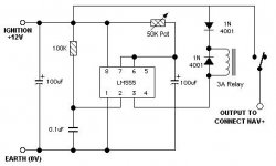
Below is a circuit diagram of the time delay unit:

To build this circuit, I ordered all the parts from Rapid Electronics (www.rapidonline.com). Their part numbers and details are listed below:
11-0015 100U 16V AXIAL ELECTROLYTIC (RC) x2
22-0150 8 PIN 0.3IN DIL SOCKET
62-0604 PACK 100 100K 0.5W CF RESISTOR (RC)
34-0505 64 X 95MM STRIPBOARD (RC)
30-1900 56X31X24MM BLACK ABS BOX (RC)
68-0276 19MM MULTITURN CERMET POT 50K(RC)
82-0336 NE555 SINGLE TIMER (RC)
08-0235 100N CERAMIC DISC CAPACITOR (RC)
47-3130 1N4001 1A 50V SILICON RECTIFIER DIODE RC x2
60-5044 3A PCB FORM A POWER RELAY - 12V (RC)
The list above includes a neat little ABS box to house everything in; you might want to order the next size-up, but we managed to get it all in this box. I would only recommend doing this if you are experienced enough, otherwise it may be worth paying the extra £20 or so to get the pre-assembled unit.
The +12V feed for the time delay is your ignition feed, taken from a location of your choice (the cigarette lighter is recommended with an in-line fuse). It shouldn't draw any major current, so a 3A fuse will be sufficient.
The 0V earth for the unit can be taken from the earth (black wire) on the main ISO power connector for the radio / CN+.

