Alternator bearings and/or voltage regulator replacement.
Can be real P.I.T.A., so it's not for complete noobies...
It's a "UniPoint" brand, almost exact copy of some Magneti-Marelli models.
Reason for repair: low charging voltage and bearings noise ("whine").
Reconditioning was done in 2012, so, some details are lost (forgotten). Also pictures are mostly low-res.
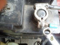
0. Unplug battery, negative terminal first (because there is a danger of making a short-circuit when you manipulate at positive one first).
1. Unbolt the alternator, 3 bolts (expect 16 and/or 17 mm hex).
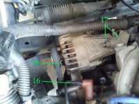
2. Check condition of the belt. If want to replace it, you must remove the "TDC (crankshaft) sensor" (one 10 mm hex).
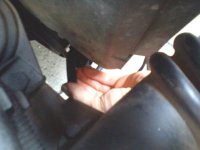
3. Carefully undo cables, main positive lead (B+) and smaller (D+). Mine is modified (D+), connector added. It can spin (whole terminal/post) inside alternator (there is a nut inside), and you will not be able to undo original cable (and remove the alternator from the car). So, solution is to cut it.
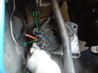
4. Next remove the plastic cover. Electrical terminals can hold it too (don't remember).
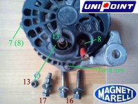
5. Voltage regulator exposed. Undo small screws and remove regulator, mind the brushes (don't break 'em).
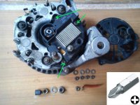
6. Regulator removed (without damage).
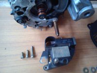
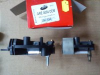
7. There can be difference when you buy not exact type, but similar. Since this is a copy of Magneti-Marelli, there was a problem to pinpoint exact model (or this was "correct" one, in theory, but it looked different - don't remember). Most alternators (within one particular car model/generation) are very similar, so "wrong" regulator should fit and work properly. Believe it or not.
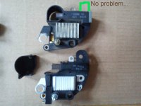
8. There are differences, but it is basically the same, it should be fine.
9. Next move is to remove pulley. Beginners often fail here.
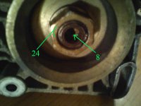
10. It is hard to just undo the nut like that.
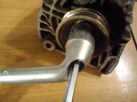
11. You could use an impact gun, but if you don't own one, you can mimic it by using hammer. BUT, you must hold a pulley firmly. AND not destroy it. Prepare "soft jaws", wood is perfect. Pressure (vise) cannot be applied to the edges (shoulders), you will crack a pulley. So be careful. If you use impact, you should hold the pulley anyway (because impact, shock, vibrations can damage rotor windings). Your job is to remove a nut (and not "jerk" the rotor).
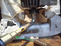
12. Pulley removed (safely to alternator internals).
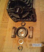
13. Next thing can be de-soldering a "rectifier bridge". Three connections.
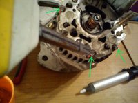
14. Solder removing tool (desoldering vacuum "sucker" pump) is very helpful.
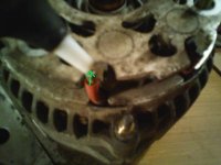
15. Diodes bridge desoldered. We go deeper, undo next bolts.
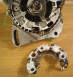
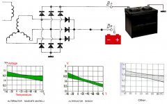
16. But, bridge is worth checking. Bridge in reverse direction (no reading).
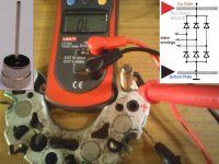
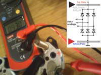
17. Bridge in forward direction (double voltage drop). Multimeter in "diode test" range/mode.
18. Then check all 3 "bottom" diodes, separately.
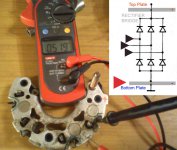
19. Then "top" ones.
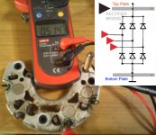
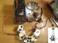
20. You get the idea. Now repeat the same tests, but under power. Pass some amps through diodes, using 12 V battery and bulb (high power, like 21 Watts or more).
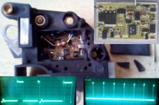
21. Regulator is a "PWM" (Pulse Width Modulation) type one. Mine was working "fine" at first glance, but voltage regulation range went down. Is it a bug or feature ("planned obsolescence")?
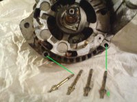
22. Bolts mentioned in step 15 removed.
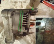
23. Now you can gently separate alternator case (two halves).
24. In case you've never heard of it, voltage regulators are temperature dependent. It's a feature, to speed up charging (chemical reactions) when cold, and protect battery form "boiling" electrolyte when it's hot under the hood/bonnet. So, next time you judge your charging level (voltage), mind the temperature...
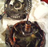
25. Casing halves separated. Smaller bearing exposed.
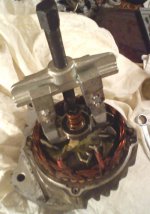
26. You can uninstall it using bearing puller. Easy one...
27. Next one can be traumatic experience to some of you. There is a retainer plate inside alternator, and you cannot just push everything out (rotor with bearing). You must try to push the rotor out of the bearing. You must be able to judge forces applied, and know when to stop (to avoid casing damage).
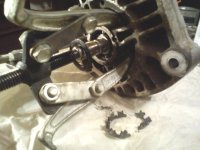
28. If it's seized, try to apply some heat (miniature gas torch). Spraying WD-40 or similar stuff is pointless (only making a mess).
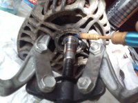
29. Next option is to remove balls from bearing. Note, you cannot dismantle bearing classic way (you remove cage, group all balls together, and move inner race sideways = bearing disassembled), because rotor is trapped inside stator (so, you can't make side/sideways move). Use some small grinder ("die grinder"), to create a notch, undercut, channel to extract the balls.
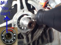
30. Remove most of the balls...
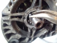
31. Finally, rotor and stator separated. But inner race is still on rotor shaft.
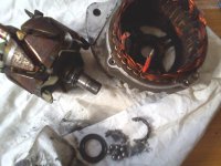
32. You can try to cut it (not entire thing, don't cut the shaft, you'll weaken it) and pull or break it somehow.
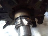
33. Bigger bearing (pulley side) retainer plate. Bolted from inside (bad design)!
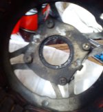
34. Inner race can be punched-out of the shaft, but be careful (shock, impact is harmful to the rotor).
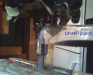
35. Nice thing is a "bearing separator" like that...good to have one or improvise.
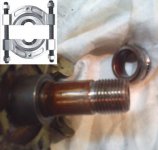
36. Small, retainer plate screws can be seized. Good method is to push hard (whole body weight) on the screwdriver and turn it with wrench. Again, impact is not advisable.
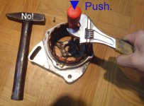
37. Big bearing outer race/ring is pressed into alternator case. Find suitable washer, bushing, big nut, whatever, and push/tap it out.
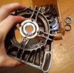
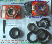
38. Surprise. Some of the bearings in the automotive industry are special. In this case (alternators), one can be special bore size (diameter). You must be able to check (measure) it (good calipers or micrometers, ID, OD). Do not use any abrasives unless you really know what the heck you are doin'. You can spoil the bearing fit (press fit will turn into loose fit, despite of normal/special bore size issue). So, DO NOT rub the rotor shaft with sandpaper, etc. Bad practice.
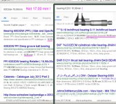
39. Example Google search screenshot. Yes, special bore bearings do exist.
40. If you know what bearings your alternator has, and you've bought them, it's time to install. Using press (any type, professional or improvised one, vise, bolt & nut) is better for reasons mentioned earlier (vibrations are damaging).
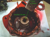
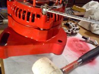
41. Big bearing and retainer plate installed. Good time to clean and paint the alternator if you like.
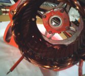
42. Now, smaller bearing. Again, better find a way to press it, not punch it into place (rotor windings damage is a number one danger here).
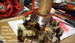
43. Installing rotor into big bearing can be tricky. You should apply force only into race that is being installed, so inner race in this case (support it with suitable bushing, piece of pipe, whatever, and then push rotor).
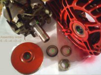
44. Assembly process in reverse order to disassembly ("captain obvious").
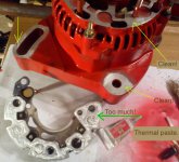
45. If you paint or not, clean the surfaces indicated, to ensure electrical contact. You can also put some thermal grease under the rectifier bridge (some will consider this "overkill"), but be moderate (there is too much of it on the picture, use half amount of that).
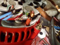
46. Time to solder back the bridge. If you break something, try to repair. I broke the post/terminal, and repaired it with piece of copper (thin sheet).
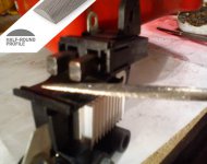
47. You can "start" brand new brushes, with some half-round file or something like that. Not necessary step, but it's a nice touch. This helps new brushes to perform better from the get-go. It's like "break-in" procedure.
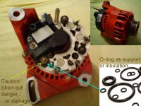
48. Important step, when you have "wrong" (in theory) regulator, extra or no "ears", electrical connections in different spots, etc. You must look closely when you install it slowly. Mind if something is deforming (will break soon - stop cranking), so you must add some mechanical support (and mind the electrical part - can your "support" be metal washer or must be insulating material, like an o-ring). I don't remember why and where exactly, but there was a need to put something under the regulator "ear". Be careful.
49. By the way. Common problem with these alternators (all Punto generations, 1, 2, and Grande). Water will eventually kill it (unfortunate placement, position in the engine bay/compartment).
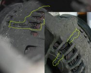
50. Test results, Before & After. It was done "twice" (first repair was regulator only, second attempt covered also bearings and cleaning, painting, thermal grease).

51. Job was done in 2012, and alternator worked properly 5 years until I've killed it (in 2017), by driving into deep puddle. As you can see, DIY repair can be pretty long-lasting. It's worth the hassle.

So, next time your alternator fails/misbehave, you can try to fix it by yourself.
Can be real P.I.T.A., so it's not for complete noobies...
It's a "UniPoint" brand, almost exact copy of some Magneti-Marelli models.
Reason for repair: low charging voltage and bearings noise ("whine").
Reconditioning was done in 2012, so, some details are lost (forgotten). Also pictures are mostly low-res.
0. Unplug battery, negative terminal first (because there is a danger of making a short-circuit when you manipulate at positive one first).

1. Unbolt the alternator, 3 bolts (expect 16 and/or 17 mm hex).

2. Check condition of the belt. If want to replace it, you must remove the "TDC (crankshaft) sensor" (one 10 mm hex).

3. Carefully undo cables, main positive lead (B+) and smaller (D+). Mine is modified (D+), connector added. It can spin (whole terminal/post) inside alternator (there is a nut inside), and you will not be able to undo original cable (and remove the alternator from the car). So, solution is to cut it.

4. Next remove the plastic cover. Electrical terminals can hold it too (don't remember).

5. Voltage regulator exposed. Undo small screws and remove regulator, mind the brushes (don't break 'em).

6. Regulator removed (without damage).

7. There can be difference when you buy not exact type, but similar. Since this is a copy of Magneti-Marelli, there was a problem to pinpoint exact model (or this was "correct" one, in theory, but it looked different - don't remember). Most alternators (within one particular car model/generation) are very similar, so "wrong" regulator should fit and work properly. Believe it or not.

8. There are differences, but it is basically the same, it should be fine.

9. Next move is to remove pulley. Beginners often fail here.

10. It is hard to just undo the nut like that.

11. You could use an impact gun, but if you don't own one, you can mimic it by using hammer. BUT, you must hold a pulley firmly. AND not destroy it. Prepare "soft jaws", wood is perfect. Pressure (vise) cannot be applied to the edges (shoulders), you will crack a pulley. So be careful. If you use impact, you should hold the pulley anyway (because impact, shock, vibrations can damage rotor windings). Your job is to remove a nut (and not "jerk" the rotor).

12. Pulley removed (safely to alternator internals).

13. Next thing can be de-soldering a "rectifier bridge". Three connections.

14. Solder removing tool (desoldering vacuum "sucker" pump) is very helpful.

15. Diodes bridge desoldered. We go deeper, undo next bolts.

16. But, bridge is worth checking. Bridge in reverse direction (no reading).

17. Bridge in forward direction (double voltage drop). Multimeter in "diode test" range/mode.

18. Then check all 3 "bottom" diodes, separately.

19. Then "top" ones.

20. You get the idea. Now repeat the same tests, but under power. Pass some amps through diodes, using 12 V battery and bulb (high power, like 21 Watts or more).

21. Regulator is a "PWM" (Pulse Width Modulation) type one. Mine was working "fine" at first glance, but voltage regulation range went down. Is it a bug or feature ("planned obsolescence")?

22. Bolts mentioned in step 15 removed.

23. Now you can gently separate alternator case (two halves).

24. In case you've never heard of it, voltage regulators are temperature dependent. It's a feature, to speed up charging (chemical reactions) when cold, and protect battery form "boiling" electrolyte when it's hot under the hood/bonnet. So, next time you judge your charging level (voltage), mind the temperature...

25. Casing halves separated. Smaller bearing exposed.

26. You can uninstall it using bearing puller. Easy one...

27. Next one can be traumatic experience to some of you. There is a retainer plate inside alternator, and you cannot just push everything out (rotor with bearing). You must try to push the rotor out of the bearing. You must be able to judge forces applied, and know when to stop (to avoid casing damage).

28. If it's seized, try to apply some heat (miniature gas torch). Spraying WD-40 or similar stuff is pointless (only making a mess).

29. Next option is to remove balls from bearing. Note, you cannot dismantle bearing classic way (you remove cage, group all balls together, and move inner race sideways = bearing disassembled), because rotor is trapped inside stator (so, you can't make side/sideways move). Use some small grinder ("die grinder"), to create a notch, undercut, channel to extract the balls.

30. Remove most of the balls...

31. Finally, rotor and stator separated. But inner race is still on rotor shaft.

32. You can try to cut it (not entire thing, don't cut the shaft, you'll weaken it) and pull or break it somehow.

33. Bigger bearing (pulley side) retainer plate. Bolted from inside (bad design)!

34. Inner race can be punched-out of the shaft, but be careful (shock, impact is harmful to the rotor).

35. Nice thing is a "bearing separator" like that...good to have one or improvise.

36. Small, retainer plate screws can be seized. Good method is to push hard (whole body weight) on the screwdriver and turn it with wrench. Again, impact is not advisable.

37. Big bearing outer race/ring is pressed into alternator case. Find suitable washer, bushing, big nut, whatever, and push/tap it out.

38. Surprise. Some of the bearings in the automotive industry are special. In this case (alternators), one can be special bore size (diameter). You must be able to check (measure) it (good calipers or micrometers, ID, OD). Do not use any abrasives unless you really know what the heck you are doin'. You can spoil the bearing fit (press fit will turn into loose fit, despite of normal/special bore size issue). So, DO NOT rub the rotor shaft with sandpaper, etc. Bad practice.

39. Example Google search screenshot. Yes, special bore bearings do exist.

40. If you know what bearings your alternator has, and you've bought them, it's time to install. Using press (any type, professional or improvised one, vise, bolt & nut) is better for reasons mentioned earlier (vibrations are damaging).

41. Big bearing and retainer plate installed. Good time to clean and paint the alternator if you like.

42. Now, smaller bearing. Again, better find a way to press it, not punch it into place (rotor windings damage is a number one danger here).

43. Installing rotor into big bearing can be tricky. You should apply force only into race that is being installed, so inner race in this case (support it with suitable bushing, piece of pipe, whatever, and then push rotor).

44. Assembly process in reverse order to disassembly ("captain obvious").

45. If you paint or not, clean the surfaces indicated, to ensure electrical contact. You can also put some thermal grease under the rectifier bridge (some will consider this "overkill"), but be moderate (there is too much of it on the picture, use half amount of that).

46. Time to solder back the bridge. If you break something, try to repair. I broke the post/terminal, and repaired it with piece of copper (thin sheet).

47. You can "start" brand new brushes, with some half-round file or something like that. Not necessary step, but it's a nice touch. This helps new brushes to perform better from the get-go. It's like "break-in" procedure.

48. Important step, when you have "wrong" (in theory) regulator, extra or no "ears", electrical connections in different spots, etc. You must look closely when you install it slowly. Mind if something is deforming (will break soon - stop cranking), so you must add some mechanical support (and mind the electrical part - can your "support" be metal washer or must be insulating material, like an o-ring). I don't remember why and where exactly, but there was a need to put something under the regulator "ear". Be careful.

49. By the way. Common problem with these alternators (all Punto generations, 1, 2, and Grande). Water will eventually kill it (unfortunate placement, position in the engine bay/compartment).

50. Test results, Before & After. It was done "twice" (first repair was regulator only, second attempt covered also bearings and cleaning, painting, thermal grease).

51. Job was done in 2012, and alternator worked properly 5 years until I've killed it (in 2017), by driving into deep puddle. As you can see, DIY repair can be pretty long-lasting. It's worth the hassle.

So, next time your alternator fails/misbehave, you can try to fix it by yourself.

