Technical Boot lock problem

Currently reading:
Technical Boot lock problem

Liam1804

Member
Joined
Feb 23, 2019
Messages
128
Points
97
Hi guys, I’m sorry about this post because This problem I’ve got
Is a common problem with the GP

The boot lock has stopped working today, I think I’ve found the issue but I could be wrong,

the reading ive got from wiring connector using a multimeter (disconnected from the lock mechanism)

Pin 1 12.7v
Pin 2 (boot light signal) - This works
Pin 3 negative
Pin 4 0v but I get 12v when I press the button on the dash or fob to open)


I’ve tested the negative wire by doing the following, I connected the multimeter black wire to a ground on the car, then connected the red wire of the multimeter to pin 3 and checked continuity, and there wasn’t an open line, so am I correct to say the negative pin is fine?

Pin 2 works fine for the boot light,


Here the problem, When I connect the wiring connector back to the lock mechanism I get the following, (I’ve taken the cover off the lock,

Pin 1 12.7v (lock in closed position)
Pin 2 works for micro switch
Pin 3 Ground
Pin 4 is also giving a ground like pin 3,


I’m no auto electrician so electrics ain’t my thing, but does this sound like the pins 3 & 4 are shorting out when connected to the lock? Because when connected there no 12.7v on pin 4 when triggered with fob or dash button to release boot,


Hope I make some sort of sense


Chris
 
Hi Chris,

- disconnect the plug
- hook a 21w bulb between pins 3 & 4
- activate the lock: the bulb should light
- reconnect the plug
- connect TWO 5W bulbs between pins 1 & 2 and positive of the car
- one should lit
- activate the lock: bulbs status should revert...

Hope this make sense.

Be aware that measuring voltages with NO load is not the best way to do it, the very few mA (µA?) from the multi-meter won't make any significant voltage drop in case of bad grounding.

If the grounding is not correct, you may have a "return path" from the motor to some floating ground via the microswitch wires. I suspect the body/boot junction to be deffective, open the rubber thing and inspect for broken/naked wire.

BRs, Bernie

If someone here helped You fix -or better, understand- your issue, hit the thanks icon @ bottom right corner, it's free and makes us feel helpy ;-)
 

Attachments

  • Boot opener diagram.JPG
    Boot opener diagram.JPG
    72 KB · Views: 137
  • boot repair kit.jpg
    boot repair kit.jpg
    25.2 KB · Views: 78
Last edited:
Thanks Bernie I’ll give that ago tomorrow with the bulb test,

A few months ago I redone the wiring in the rubber grommet with silicone wire so that’s all sound,

however today I decided to cut the black tape that’s wrapped around the wires by the connector plug, it looked like the tape was from factory but I Discovered somebody has previously done a repair with the wires and some was expose but I wouldn’t have spotted this if I didn't remove the tape because it looks factory,

I’ve managed to get another 4pin wiring connector with 7 inches of wire attached so I’ll cut the old one off and re-wire this new one and fingers crossed ? it should be ok with the new lock

I’ll post an update

Chris
 
Last edited:
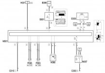
Bernie, I’ve just been reading over your reply again and looking at the wiring diagram, am I correct to say pins 1&2 operate the boot light and the dashboard warning light?
 
Last edited:
Bernie, I’ve just been reading over your reply again and looking at the wiring diagram, am I correct to say pins 1&2 operate the boot light and the dashboard warning light?

Hi Chris,

you're right, pins 1&2 inform the Body Computer Module of the hatch status, which in turn switches the boot and warning lights. The two other pins are for grounding and positive feed to releasing motor ...

BRs, Bernie

If someone here helped You fix -or better, understand- your issue, hit the thanks icon @ bottom right corner, it's free and makes us feel helpy ;-)
 
Update, FIXED,

Putting a test light on pin4 then activating the boot release nothing happened, I thought that’s strange because I’m sure the multimeter was reading 12v on pin4, After double checking it was reading MV not volts, So I started tracing the wire back while testing at different points, I removed all the trim were the boot light is and noticed there was another piece of wire that somebody had soldered in, put the test light on the join and the test light Lit up when activating the boot, BINGO I had found the problem, I then tried the same method with the other end of the wire but nothing happened, so that joining of wire must of been bad, Cut that piece out and re joined the ends and Hey presto the boot release now works,

Bit of a bummer though because I brought a new lock thinking it was that, least I’ve learnt one thing, triple check the voltage readings next time, ?. Thanks Bernie for that wiring diagram
 
Thanks for the update (Wil?)Liam and congrats for your pugnacity !! I'm happy you and maybe some others have learnt the "under load" troubleshooting method...

Feeling proud no ;-) ??


Bets regards, Bernie.
 
Last edited:
Back
Top