Hi,
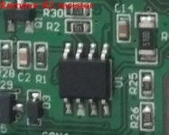
I've recently acquired a ELM327 chinese clone I made a modification for switching between 1-9 (it works like yellow adapter) to 6-14 Can lines .
If I use pins 1-9 can access to (AC, Body COmputer, Dashboard) etc. everything that is using these lines.
But if I switch to 6-14 line to access (ABS, Engine etc) can't connect the program throws check cable connection, I've tried to decrease serial port latency but it still not working.
Body computer showed this error I cleared and it disappeared.
Any ideas?
I've recently acquired a ELM327 chinese clone I made a modification for switching between 1-9 (it works like yellow adapter) to 6-14 Can lines .
If I use pins 1-9 can access to (AC, Body COmputer, Dashboard) etc. everything that is using these lines.
But if I switch to 6-14 line to access (ABS, Engine etc) can't connect the program throws check cable connection, I've tried to decrease serial port latency but it still not working.
Body computer showed this error I cleared and it disappeared.
1: U0019 - B-CAN line - intermitent
The CAN data communication line (Controller Area Network) between different vehicle ECUs does not work correctly.
The CAN BUS is a connection between ECUs which enables them to share information and synchronize the function of the different systems. Depending on the vehicle, the CAN line can link the engine, ETC, ESP, ABS, Immobilizer, AirBag (SRS), A/C system (CC) etc.
Check the harness between the ECUs for opens, shorts and weak connections, and ripple free power and good ground supplies to the ECUs.
Ensure that no additional equipment emitting strong radio or magnetic fields is installed close to the ECU wiring (car telephone, stereo speaker wires etc.)
The fault is intermittent. Clear fault codes, and observe for future appearance of the same fault. Dashboard warning light was not activated for this fault.
Any ideas?