Technical wiring diagram

Currently reading:
Technical wiring diagram

paullap

Member
Joined
Oct 19, 2017
Messages
134
Points
79
Hi I am working on a mate's Grand Punto 2008 1.4 petrol auto.
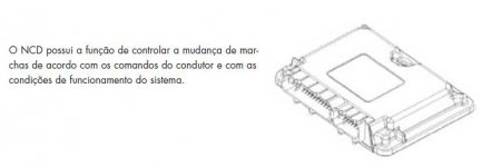

Gearbox problems

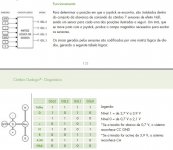
Codes P060C control unit faulty (microprocessor)
p1772 Gerashift lever switches ( one of 4)


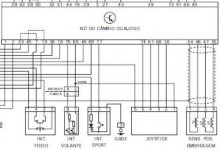
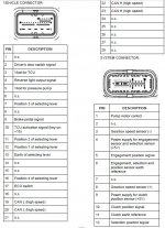
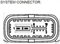
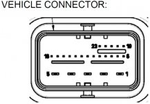
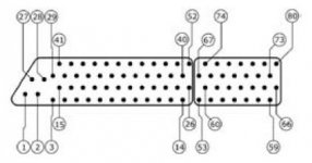
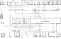
Does any one have a wiring diagram for the actuator please, I have access to Autodata but they have nothing on the auto

I could do with the diagram and pin data if possible

or any other information on this problem please


Paul
 
Try the eLearn manual... Available in the forum's download section.
It should have all the modules and the wiring. might be more difficult with the auto.
 
It is quite hard to find specific informations about the Dualogic system and there is very little about it, if any, in eLearn.

Anyway, the gear-lever is built around 10 Hall-effect sensors whose status are internally converted to four analogue signals going to the AMT controler. No clue what those signals are/should be :-(

The attached drawing might not be the correct one so be carefull with using it !

BRs, Bernie

If someone here helped You fix -or better, understand- your issue, hit the thanks icon @ bottom right corner, it's free and makes us feel helpy ;-)
 

Attachments

  • Dualogic user interface.JPG
    Dualogic user interface.JPG
    59.6 KB · Views: 394
  • Dualogic controller pinout.JPG
    Dualogic controller pinout.JPG
    91.5 KB · Views: 413
  • Dualogic system connector.JPG
    Dualogic system connector.JPG
    46.4 KB · Views: 266
  • Dualogic vehicule connector.JPG
    Dualogic vehicule connector.JPG
    56.1 KB · Views: 279
Thanks for that drawing Bernie, that will be helpful. I really could with some help from someone that can help me understand the live data readings.


Paul
 
Hi Paul,

I bet you'd be pleased with the attachment … and google translate will surely help ;-)

BRs, Bernie

If someone here helped You fix -or better, understand- your issue, hit the thanks icon @ bottom right corner, it's free and makes us feel helpy ;-)
 

Attachments

  • Dualogic gearlever logic.JPG
    Dualogic gearlever logic.JPG
    79.2 KB · Views: 248
Here's what Google Translate says:

Operation:

To determine the position where the joystick is located, 7 Hall effect sensors are installed inside the shift control lever assembly, one sensor for each of the positions shown below. A magnet, which moves along with the joystick, produces the magnetic field needed to excite the sensors.

The signals generated by the sensors are encoded by a logic diode array, generating the following logic table:

Level 1 = from 2.7 V to 3.9 V
Level 0 = from 0.7 V to 2.1 V
* If the voltage is below 0.7 V, the system recognizes CC GND
* If the voltage is above 3.9 V, the system recognizes AC

BRs, Bernie

If someone here helped You fix -or better, understand- your issue, hit the thanks icon @ bottom right corner, it's free and makes us feel helpy ;-)
 
Hi Bernie, I can see it changing from N to auto and Reverse on live data, but nothing is physically moving on the gear box.


Regards


Paul
 
Paul, do you have THIS type of connector or the one I already sent … ?
 

Attachments

  • Dualogic connector 2.JPG
    Dualogic connector 2.JPG
    23.7 KB · Views: 69
Last edited:
Hi Bernie, Are we talking auto ecu inside the car behind the glove box?. Because i have not had that out yet.


Regards


Paul
 
Nope, gearbox controler … should be located on the robot itself or nearby
 
Last edited:
Hi Mate, I need ti find where this is located. So just to recap

Engine ECU, I know where that is
Gear Box ECU ? I have ti find it


Body control module That is what is inside the car behind the glove box?

REgards


Paul
 
Hi Paul, follow the harness from gearbox sensors & valves and You'll find the controler… and You're right, the Body Computer is the one behind the glovebox (on RHD cars).

BRs, Bernie

If someone here helped You fix -or better, understand- your issue, hit the thanks icon @ bottom right corner, it's free and makes us feel helpy ;-)
 
Hi Bernie, Thanks for that, Just one more question please, Do you know if any of these parts, ie Gearbox ECU, actuator, are interchangable or are they coded to the car?. I have done many Corsa easytronics, but not the Punto's.


Enjoy your sunday


Paul
 
Hi Paul, to my understanding the parts are all interchangeable, as far as you don't touch the ECU (engine control unit) or the BCM (body computer module) or the identifier you should not have to "zero" any data.
BUT: there are datas stored in the gearbox controler so there is a procedure that needs to be run after part(s) replacement, there are also "tricks" to know when replacing position sensor(s)…
Have you got MES to read the stored codes in the GB controler ?

As it is very involved with the controler logic, I would definitely inspect the brake switch and its wiring/connection to the BCM !!

BRs, Bernie

If someone here helped You fix -or better, understand- your issue, hit the thanks icon @ bottom right corner, it's free and makes us feel helpy ;-)
 
Found a much better quality wiring diagram …

BRs, Bernie

If someone here helped You fix -or better, understand- your issue, hit the thanks icon @ bottom right corner, it's free and makes us feel helpy ;-)


edit: replaced picture
 

Attachments

  • Dualogic wiring3.JPG
    Dualogic wiring3.JPG
    158.6 KB · Views: 881
Last edited:
Hi Bernie, That is brilliant, I will mark out the power and grounds and check them tomorrow as the car is at work.

Many Many Thanks


Paul
 
Back
Top