Hi Alan,
I re-read your post, you say that you can hear a click in the relay box when trying to crank the engine; you say also that the starter would crank if you short the small wire @ + with a screwdriver: that prove the starter motor is good aswell as the "puller". Your issue seems to come from the command itself, here's how it works (excerpt from eLearn):
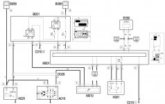
FUNCTIONAL DESCRIPTION
The Body Computer M1 - connector G - is supplied directly from the battery from a line protected by maxifuse F2 of engine compartment control unit B1. It is ignition-operated (INT) at pin 32 of connector D. Pin 10 of connector H of M1 supplies a reference earth to the Body Computer.
Power distribution to the vehicle (INT "ignition-operated, INT/A, "AVV", etc) is managed by the Body Computer that is connected to ignition switch H1:
- ignition switch H1 is supplied by the Body Computer from pin 48 of connector D of M1 via a line protected by fuse F85;
- ignition switch H1 sends ignition-operated signal “15/54” to Body Computer M1 at pin 32 of connector D.
When the ignition key H1 is turned to its furthest position (START) - pin 50 - power is sent to the electromagnetic winding - pin 50 - if starter motor A20 - in accordance with the control strategy described previously:
- the ignition switch H1 sends a START signal to Body Computer M1 at pin 31 of connector D; and this in turn sends an enablement request to engine control unit M10 via the CAN;
- start-up takes place only in the presence of an enablement signal - from pin 40 of connector A of engine control unit M10: this energizes the start-up enablement relay T18, located in the engine compartment control unit B1: the relay - supplied by an ignition-operated supply from a line protected by fuse F35 and relay T6 of B1: this ignition-operated supply (INT) is controlled from pin 1 of connector A of M1;
- the start-up enablement relay T18 of B1 then sends a power supply to pin 50 of starter motor A20.
Pin 30 of A20 - connector A - i.e. the actual motor, receives a power supply with the voltage coming directly from the battery A1.
The direct current generated by alternator A10 (pin B+) - connector B - is sent to battery A1 via the MAXIFUSE box on the battery, passing through motor A20.
When the alternator does not turn and does not therefore recharge the battery, an earth signal is sent from pin D+ - connector A - of A10 to engine control unit M10 - pin 19 of connector A: this is connected via the CAN line to Body Computer M1 and to instrument panel E50 and manages, as described above, activation of the generator warning light on the instrument panel.
According to this description and the attached drawing, I believe F35 or a bad T18 relay are good candidates ...
BRs, Bernie
If someone here helped You fix -or better, understand- your issue, hit the thanks icon @ bottom right corner, it's free and makes us feel helpy ;-)