Technical Centre Console Blank Switches
- Thread starter BrendRowe
- Start date
Then eLearn has wrong diagrams !?
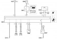
Here is an excerpt of the 14 Tjet section, it clearly shows direct connection from the Panel Switch 's PB (H090) to the body computer (M001), strange ...
BRs, Bernie