Technical Multiecuscan adapter yellow problem

Currently reading:
Technical Multiecuscan adapter yellow problem

omega22

New member
Joined
Dec 24, 2011
Messages
31
Points
10
Location
Toledo
Hello,
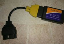
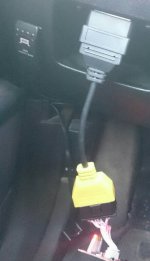
I have a registered version of MultiEcuScan, an ELM327 interface and i've just bought a yellow cable.
My ELM327 is working fine with MultiEcuScan for all features that don't required an additionnal cable (Engine is working fine for example). I've done an oil change, and thus I want to reset the service interval. This is the reason why i bought a yellow cable

Unfortunately, my yellow cable doesn't work. I have the message : elm327->ecu Connection failed!
Do you think that it is not working because of my ELM327 interface? Even if my ELM327 works fine for Engine in MultiEcuScan? If I have the resistor problem with my interface (it's a cheap version), should my ELM327 work with the Engine part?
Or is it because of my yellow cable? How can I test my yellow cable?

thanks

Does MES ask for the yellow adapter on connection? If not, don't need it.
 
Hi,
What year and engine?
To answer others questions first, yes you do need adaptor 3 (yellow) for service reset on GPs.
Most likely problem is a dodgy chinese ELM 327 interface. These have a CAN termination resistor across the bus that should not be there. If you have a multimeter, check the resistance between pins 6 and 14 on the interface (no adaptor) if it is less than 500 ohms (should be much more if OK) you have a resistor fitted. Typical value is 120 ohms. If you can use a soldering iron you can open the interface, trace the resistor and remove it.
Otherwise buy a good interface e.g http://www.ebay.co.uk/itm/271275445368 (I've used this seller).

HTH,
Robert G8RPI.
 
Last edited:
This post contains affiliate links which may earn a commission at no additional cost to you.
Hi All,

have been using a Chinese clone ELM327 I/F w/o problem on the ECu and ABS unit. For other nodes, MES was asking for the yellow plug so I modified the I/F to match the 1-9 pins CAN bus that Fiat uses in // with the ECU CAN and still couldn't communicate with the other nodes :-(

The solution was to remove the CAN bus termination resistor on the I/F PCB; no need to add new R/C network (noise filtering) as described on few threads, only need to remove that f** resistor shunting pins 6&7 of the CAN chip. One have to follow OBD pins 6&14 (ECU CAN) tracks on the PCB and eventually find the bad girl; this will be marked 121, which mean 12 followed by 1 zero = 120 ohms, which is the recommended value for a CAN termination resistor. But as the OBD port is not at either end of the CAN network, it doesn't have to be terminated, but termination resistor there prevents good, or any, communication ...

Regards, Bernie

If someone here helped You fix or understand your issue, hit the thanks icon, it's free !!
 
Last edited:
As just said above, had the exact same problem, and the fix was exactly the same. Spend ages checking the connections in the yellow cable and comparing them with MES site, while the single resistor was the problem. On some boards it is tricky to access and a shortcut brutal force might be needed to get rid of it.
 
<SNIP> no need to add new R/C network (noise filtering) as described on few threads, only need to remove that resistor shunting pins 6&7 of the CAN chip. <SNIP>

/
The R/C network that some people add is still a terminator but does not pass DC current so does not have such a bad effect, but it should not be fitted. There should only be two teminators and they are part of the car. It's not 100% clear why the interfaces work on the normal OBD connection but not all the optional ones. It is likey because the optional connection has more nodes and more cable connected in the car. Each node and length of cable adds a bit of load and the terminator pushes it over the edge and stops working. On some cars the OBD main CAN connection is a dedicated bus and only has one terminator fitted. As long as the OBD reader interface does not have a long cable (not the USB lead) the lack of a second terminator has no effect on this bus. It's all to do with reflections on unterminated transmission lines and if the cable (transmission line) is short compared to the CAN bus speed (1/wavelength) it has no effect.

Robert G8RPI.
 
Hello,
I have a registered version of MultiEcuScan, an ELM327 interface and i've just bought a yellow cable.
My ELM327 is working fine with MultiEcuScan for all features that don't required an additionnal cable (Engine is working fine for example). I've done an oil change, and thus I want to reset the service interval. This is the reason why i bought a yellow cable

Unfortunately, my yellow cable doesn't work. I have the message : elm327->ecu Connection failed!
Do you think that it is not working because of my ELM327 interface? Even if my ELM327 works fine for Engine in MultiEcuScan? If I have the resistor problem with my interface (it's a cheap version), should my ELM327 work with the Engine part?
Or is it because of my yellow cable? How can I test my yellow cable?

thanks
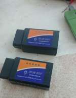
Hi, that happened to me. You MUST use a ELM327 1.5 with chip "pic18f25k80".

Take a look of this:
http://s.aliexpress.com/MFZFRZR7

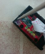
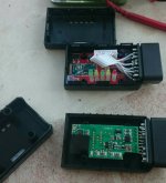
Then, you need to open it:
_20170323_042350.JPG

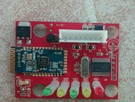
Remove glue and get the board out of box. You can use screwdriver and hair dryer to remove it:
_20170323_042336.JPG

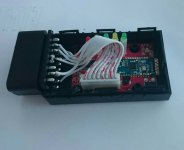
Then remove wires:
_20170323_042318.JPG

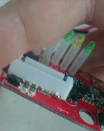
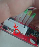
With a flat screwdriver, move up a bit wire connectors on board, until you can see a small resistor under them. On that resistor, it should be a number, usually it is 121. This resistor must be on your ELM327 OBDII adapter, it depends on model, version...but, as you said that is working with nodes that dont need Yellow adapter, it means that you have a good clone or original, so if your ELM327 it is a mini version, you have to remove first board on top, where Bluetooth board is, and on the botton board, there it is on top of it, between some resistors. Use a magnifier to find your resistor. I recommend to get one like mine. It works, great quality, and easy to mod:
_20170323_042211.JPG
sketch-1490239375003.jpeg

With a soldering iron, remove that resistor from board. Then, connect everything again, and with your Yellow adapter, go to your car an check it out!
_20170323_043339.JPG
_20170323_043355.JPG
_20170323_043415.JPG
_20170323_043429.JPG
_20170323_043444.JPG
_20170323_043510.JPG
_20170323_043524.JPG
_20170323_043457.JPG
Now it works for all your system, even if you need Yellow adapter or not!

Regards,
Julio
 
Last edited:
Hola Julio,

I will not ALWAYS agree with you ! ;-)

The PIC18Fxxxxx is just a programmable device, its part# doesn't reflect what piece of SW is loaded in, so it can contain any version...
And the tuto about the resistor MIGHT be wrong, depending of the PCB used by the cloner, the termination resistor can be located in a different place. But will ALWAYS shunt pins 6&7 of the CAN controler (or pins 6&14 of the OBD connector) ...

Regards, Bernie
 
Last edited:
Hi,
What year and engine?
To answer others questions first, yes you do need adaptor 3 (yellow) for service reset on GPs.
Most likely problem is a dodgy chinese ELM 327 interface. These have a CAN termination resistor across the bus that should not be there. If you have a multimeter, check the resistance between pins 6 and 14 on the interface (no adaptor) if it is less than 500 ohms (should be much more if OK) you have a resistor fitted. Typical value is 120 ohms. If you can use a soldering iron you can open the interface, trace the resistor and remove it.
Otherwise buy a good interface e.g http://www.ebay.co.uk/itm/271275445368 (I've used this seller).

HTH,
Robert G8RPI.

GP 1.4 8V 77 cv dualogic year 2007.

The seller ebay not post to Spain??

thanks
 
Last edited:
This post contains affiliate links which may earn a commission at no additional cost to you.
GP 1.4 8V 77 cv dualogic year 2007.

The seller ebay not post to Spain??

thanks

Ahh, you do not have a country flag on your profile. You need to search for an ELM 327 USB interface that specifically states it's "modified for Multiecuscan" from you local ebay. If you are stuck I have a spare one I can sell you at cost plus postage but it may be easier for you to get it locally. or find someone who can remove the resistor from the one you have.


Robert G8RPI.
 
Hola Julio,

I will not ALWAYS agree with you ! ;-)

The PIC18Fxxxxx is just a programmable device, its part# doesn't reflect what piece of SW is loaded in, so it can contain any version...
And the tuto about the resistor MIGHT be wrong, depending of the PCB used by the cloner, the termination resistor can be located in a different place. But will ALWAYS shunt pins 6&7 of the CAN controler (or pins 6&14 of the OBD connector) ...

Regards, Bernie
Hi Bernie,

Yeah, you are right! But I said so at the tuto. Tuto tells how to do it with this adapter.
On the other hand, many sellers from eBay, AliExpress... They said that their adapter are 1.5 100% original, then, you go to AlfaOBD and you cant connect with your car.
If you dismount that clone, you will notice a few things:
First: instead a chip like PIC18F25K80, you will have a piece of black stuff on it, with an useless bunch of AT commands with a list unfinished.

Two: You will have a small CAN chip (like NCV7340) for all CAN communication.

PIC18F25K80 is a programable MCU like Arduino or similars, but you can install on it ELM327(this is the original chip) firmware. Also, PIC18F25K80 supports CAN by itself, and works along with other chip, that I think that it is MCP2515 or similar.

I said "you MUST use that chip". I mean, in case that you are buying a cheap adapter, get one with this chip.

Take a look of this, both says that they are 1.5 ELM 327:
_20170323_163347.JPG

But...take a look opened:
_20170323_163406.JPG

That is what you will find in most of cases. But what I said before, it depends on seller,model,...

Regards,
Julio
 
Last edited:
Hola Julio,

between PIC version, Firmware version, PCB version, there is too many possible combinations that one cat wouldn't find her kittys... I really doubt ANY cloner would try to implement the very cheap CAN controler on a PIC chip, so once the "plug" is opened it's quite easy to follow the PCB tracks from the CAN pins to the chip (they're straight) and identify if there is a termination resistor (terminator ? ;-) or not. Some I/F come with an R-C network, which is fine, others don't even have that f** resistor which is fine as well.
But definitely, if one want to connect to other MCU than the engine and ABS (with the yellow plug) this resistor, if present, HAS TO BE REMOVED.
BTW, you'll never know what chip's inside before you open it (after buying, of cource)...

Buenas tardes, Bernie
 
Last edited:
Ola,

if you'd red the thread, you'd know that the resistor that need to be removed is ALWAYS shunting pins 6 & 7 of the CAN ship (which is a 8 pin ship)...

On your board, that's R2.
BTW, 121 is the resistor value (12 + 1 zero = 120 ohms), not the resistor #, it's clearly marked on it !

Regards, Bernie

sorry, for some reason I can't upload picture...


Many thanks again
 
I have removed R2 and still I can not access MES
Now I can not access anything
I've tried elm on scanmaster and if it connects to the car
any ideas
I don't what to do


regards
 
Back
Top