Sub should be switching of when the headunit does. Is it an OEM unit or aftermarket 
You are using an out of date browser. It may not display this or other websites correctly.
You should upgrade or use an alternative browser.
You should upgrade or use an alternative browser.
Technical Battery Draining / GP Not Starting
- Thread starter SJB1985
- Start date
Currently reading:
Technical Battery Draining / GP Not Starting
Sub should be switching of when the headunit does. Is it an OEM unit or aftermarket
Lol good question, it is the sub from an Abarth Grande Punto that has been retrofitted. So you could say OEM with retrofitting as I didn't have any of the loom mate
It's not been fitted properly then. What are you relaying it to 
This will be the cause of your drain if it doesn't shut down with the headunit, at least you've found your issue though
This will be the cause of your drain if it doesn't shut down with the headunit, at least you've found your issue though
It's not been fitted properly then. What are you relaying it to
This will be the cause of your drain if it doesn't shut down with the headunit, at least you've found your issue though
im going to stick my neck out and as i told Steven Im going on the big bold assumption that when OEM wired its switched via the CAN network
im going to stick my neck out and as i told Steven Im going on the big bold assumption that when OEM wired its switched via the CAN network
I don't think they are but cannot be certain. I'd have thought its just got a normal signal feed from the head unit, just like any none OEM setup
well erm....
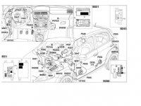
looks like it gets powered by the boot fuse box when OEM wired which doesnt exist in the lower spec cars
hell even with my electronic savvy the GP sterio with sub looks a bit like this after a couple of relaxing hours in the Hungry horse


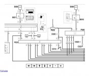
The radio P20 is supplied directly (4 of connector A) from the battery via the line for fuse F51 of the Body Computer M1.
Pin 8 of connector A is earthed.
Pins 1 and 3 of connector A connect to the CAN that connects the radio P20 to the Body Computer M1 (pins 5 and 20 of connector D) and to the other system nodes.
The Body Computer M1 is connected to the radio controls on the steering wheel via the clock spring D47: pin 35 of connector D supplies a reference earth to pin 7 of D47; pin 52 of connector D of M1 receives signals from the pushbuttons located to the left of the steering wheel while pin 50 of connector D of M1 receives signals from the pushbuttons on the left of the steering wheel.
The Body Computer M1 - connector G - is supplied directly from the battery via a line protected by maxifuse F2 of the engine compartment control unit B1; its ignition-controlled supply (INT) is received at pin 2 of connector D; pin 10 of connector H or M1 supplies the Body Computer with a reference earth.
The amplifier in the subwoofer P49 receives a direct supply from the battery - at pin 3 - via the line for fuse F67 of the fuse box in the boot B45; pin 7 of amplifier P49 is earthed.
Pin 6 of P49 is connected to the radio P20 - pin 5 of connector A - which supplies a positive enablement signal to turn on the amplifier (the aerial supply).
The amplifier P70 is supplied directly (1 of connector B) from the battery via the line for fuse F51 of the Body Computer M1.
Pin 2 of connector B is earthed.
Pin 8 of connector B of P70 is connected to the radio P20 - pin 5 of connector A - which supplies a positive enablement signal to turn on the amplifier (the same supply as for the aerial).
The cables with signals for the amplifier P70 (pins 3, 4, 9, 10 connector A and pins 1, 2, 7, 8 connector B) and for the subwoofer P49 leave connector B of P20.
The following cables with signals for the speakers leave connector A of P70;
- pins 6 and 14 to the left front speakers P35 and P45 (or P36 and P46 on right hand drive versions);
- pins 10 and 11 to the right front speakers P36 and P46 (or P35 and P45 on right hand drive versions);
- pins 4 and 5 to the left rear speaker P30;
- pins 12 and 13 to the right rear speaker P31;
looks like it gets powered by the boot fuse box when OEM wired which doesnt exist in the lower spec cars
hell even with my electronic savvy the GP sterio with sub looks a bit like this after a couple of relaxing hours in the Hungry horse

Last edited:
Lets not forget lol I fitted it so I would say theres the error lol hopefully will get it sorted lol :thumbup:
Andy Monty time for that beer!


