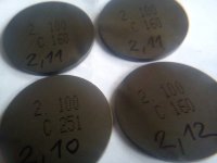
DIY valve clearance adjustment job is not that hard (just tricky). Try it!
0. Disconnect the battery (after job is done, you will have to set date and time, that's it). Then remove air filter box (as a whole or check air filter too - six, 7 mm hex screws). There are two, 10 mm hex bolts holding it. Mind the rubber hoses (two: big and small one), disconnect them. Then remove coil-pack module (three, 10 mm bolts), undo all connectors.
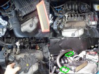
1. Undo all connectors on the engine computer and camshaft cover (earth point, brackets, etc.), or whatever you call it, "ECU". Then remove it. You don't have to, but if it's dirty, remove it for cleaning.
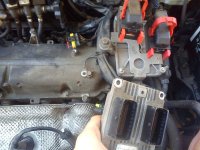
2. Next, remove ECU mount/bracket. Three bolts and one nut, all 10 mm hex. There is one weird connector, to unplug it, move grey plastic thing to the side (sideways).
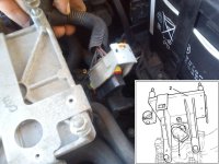
3. Unbolt and move the cambelt top cover. Three 10 mm hexes. Mind the cable inside.
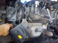
4. Remove the camshaft position sensor (not necessary, you can pop the cover with sensor installed). Visual check it (mind the o-ring, it may stay inside cover).
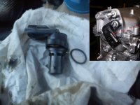
5. Same story with VVT actuator, electromagnet, whatever. Worth checking. If camshaft cover is dirty, you should clean it (then of course, all sensors, etc., must be taken out).
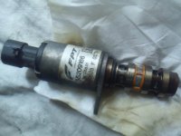
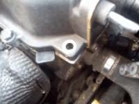
6. If you plan to replace cover gasket, it is advisable to mark and measure roughly, cover position on the engine head. If old gasket is still in one piece and it's still flexible, you don't have to change it (will not leak, don't worry).
Special service tool ("bracket", "jig", "fixture" or whatever you call it) is (may be) helpful only if you want to fit new gasket (you must "crush" it somewhat, force it into place). Worst case scenario is, that it can affect, disturb the camshaft position sensor readings. That's all. The "danger" here is mostly theoretical. Don't panic. But "just in case" measure, mark somehow cover position. Bolts are 8 mm hex (installation torque is about 8 Nm, some sources list 6-10 Nm range).
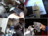
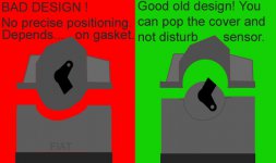
7. That's a classic design flaw (young inexperienced "wanna-be" designers, new generation). They should stay with good old design (all older models had camshaft cover removable, non interfering with ignition system parts - like mechanical distributor in oldest FIATs, or coils bracket in other). Now, "touchy" electronic sensor is installed...on "floating" cover. All depends on how new rubber will deform during cover installation = that's retarded.
8. Parts like this (covers) "like" to "seize". You will not be able to just move it by hand. It's so "stuck" like glued. You must "pop" it with some small pry-bar, screwdriver. Watch out, do not damage sealing surfaces (both sides: cover and on the engine head).
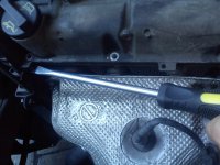
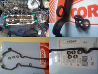
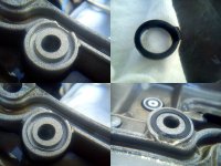
9. My cover popped out without gasket in it (gasket was "glued" to the engine head). That's a good thing, it will help align the cover, so there is no need for "special snowflake" jig/fixture. If you can, try to do that intentionally, pop the cover gently and try to keep gasket on the engine head side. One disadvantage is, you can rip the seal (small round seal, it is attached to the gasket). But that's not a big deal, they can be separated like this and installed again. If you are replacing gasket, make sure you ordered, bought, complete set (cover gasket + those small seals, technically not an "o" rings, cross-section is not round).
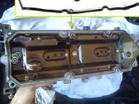
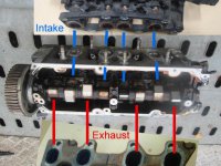
10. Engine head with camshaft exposed. Nothing special (yawn), has almost the same look for last 30 years or so (if you know the older models), it's so called "FIRE" family.
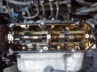
11. Valves layout. If you are not sure, just look at the manifolds (intake and exhaust). Easy.
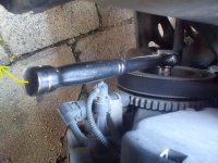
12. During procedure we will turn the engine in the normal, working direction (clockwise), do it with 15 mm socket attached to crankshaft wheel central bolt.
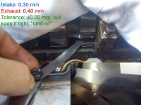
13. Finally. Clearance checking is easy. Set lobe upright and use feeler-gauges. If it drags you are spot on. Good to have 0,01 mm increment step ones (0,05 mm step is little to "coarse", but good enough). Intake clearance ("gap") should be 0,30 mm, and exhaust bigger (obviously, it heats more), 0,40 mm.
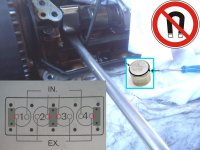
14. Removing shims for the first time is "difficult" and tricky. There are supposedly "special" tools for that, but there's no need for such toys. Just use some big screwdriver and push it between camshaft (lobe "up") and shim. Trick is, to find suitable tool to hold (block, retain) "bucket tappet". For example modified screwdriver, it must fit tight under the camshaft (between camshaft and tappet outer edge, but be careful, don't crack/chip it). Then you can gently remove the shim (there are two notches, slots where you can place some mini screwdriver, scribe, whatever, "pointy" object), it's "sucked" into tapped (oil is holding it).
Use clean tools, and you will not scratch anything (don't worry, shaft lobes and shims are hardened well). Not good to use magnets, in theory it can magnetise parts (shims, tappets) and they will collect metallic dirt and/or make abnormal moves during engine work (or opposite - not make moves like rotation, valves + tappets + shims should spin to wear evenly).
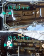
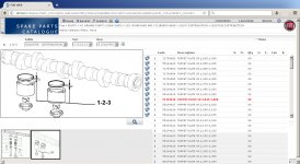
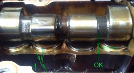
Four (indicated in red colour) shims may be even more tricky to swap, because they're partially "hidden" under camshaft bearings. Just be careful (place your home-brew tappet "retainer/block" tool, move shim little bit, and try to push tappet from the top, vertically instead of horizontally like on the picture below).
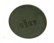
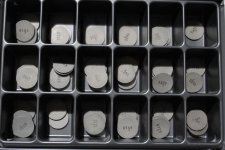
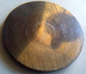
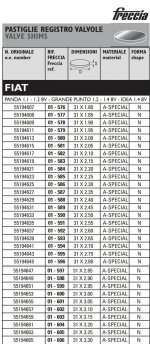
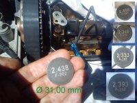
15. Shim extracted (don't turn the engine while there is no shim in the tappet). Shims are 31,00 mm diameter. Thickness, "it depends". In general it should be something around 2,5 mm. As valves are wearing out, you will need smaller and smaller shims, especially on exhaust. Of course, you remove shims (one at the time), that will be replaced (if clearance is OK, leave it alone). But, sometimes there is possibility, to swap existing shims, so it's good to know all sizes (so I've removed all, one by one).
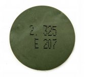
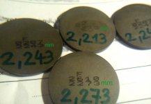
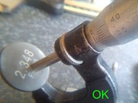
16. Random check, thickness spot-on (value as engraved on the shim). Notice, those shims are 3 decimal places (micro-meter). In the market most shims are 2 places, that's not a "problem" at all. And typical "step" will be probably 0,05 mm.
17. Write all clearances, make a chart like below. In this example all intake valves were good (no adjustment required), BUT exhaust ones are terrible (especially cylinder 1). May be trashed (burnt valve) already. Forgot to mention: car is a double fuel (petrol + LPG, not friendly to exhaust valves). That's the reason. And previous owner didn't care (didn't bother to adjust valves) probably. Calculated shim sizes are not obtainable, but there are close ones. If you can, try to put a little "too small (too thin)" shim. It's better when clearance is just a bit bigger (valves will "seat" naturally making clearance smaller).

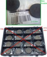
18. If you have stash of old valve shims, from older Fiat models, they're useless now. Back in the days, shims were thicker (let's say 3-5 mm range), now you need 2-3 mm range. Diameter is the same (31,00 mm).
19. There is a minimal shim thickness, you cannot adjust the valves forever. Shim must stick out of the tappet. If not, camshaft lobe will crash into tappet edge. Didn't measure (tappet shim seat depth), but in my case, values like "2,20 mm" are probably (99,9% sure) last adjustment (shim barely protrudes). Next time it's a valve job...
Guide ends here, next page and points are informational only ("conversation piece")...not so "DIY".
After adjustment car started with no problems, engine runs just fine, no error codes.

0. Disconnect the battery (after job is done, you will have to set date and time, that's it). Then remove air filter box (as a whole or check air filter too - six, 7 mm hex screws). There are two, 10 mm hex bolts holding it. Mind the rubber hoses (two: big and small one), disconnect them. Then remove coil-pack module (three, 10 mm bolts), undo all connectors.

1. Undo all connectors on the engine computer and camshaft cover (earth point, brackets, etc.), or whatever you call it, "ECU". Then remove it. You don't have to, but if it's dirty, remove it for cleaning.

2. Next, remove ECU mount/bracket. Three bolts and one nut, all 10 mm hex. There is one weird connector, to unplug it, move grey plastic thing to the side (sideways).

3. Unbolt and move the cambelt top cover. Three 10 mm hexes. Mind the cable inside.

4. Remove the camshaft position sensor (not necessary, you can pop the cover with sensor installed). Visual check it (mind the o-ring, it may stay inside cover).

5. Same story with VVT actuator, electromagnet, whatever. Worth checking. If camshaft cover is dirty, you should clean it (then of course, all sensors, etc., must be taken out).

6. If you plan to replace cover gasket, it is advisable to mark and measure roughly, cover position on the engine head. If old gasket is still in one piece and it's still flexible, you don't have to change it (will not leak, don't worry).
Special service tool ("bracket", "jig", "fixture" or whatever you call it) is (may be) helpful only if you want to fit new gasket (you must "crush" it somewhat, force it into place). Worst case scenario is, that it can affect, disturb the camshaft position sensor readings. That's all. The "danger" here is mostly theoretical. Don't panic. But "just in case" measure, mark somehow cover position. Bolts are 8 mm hex (installation torque is about 8 Nm, some sources list 6-10 Nm range).

7. That's a classic design flaw (young inexperienced "wanna-be" designers, new generation). They should stay with good old design (all older models had camshaft cover removable, non interfering with ignition system parts - like mechanical distributor in oldest FIATs, or coils bracket in other). Now, "touchy" electronic sensor is installed...on "floating" cover. All depends on how new rubber will deform during cover installation = that's retarded.

8. Parts like this (covers) "like" to "seize". You will not be able to just move it by hand. It's so "stuck" like glued. You must "pop" it with some small pry-bar, screwdriver. Watch out, do not damage sealing surfaces (both sides: cover and on the engine head).

9. My cover popped out without gasket in it (gasket was "glued" to the engine head). That's a good thing, it will help align the cover, so there is no need for "special snowflake" jig/fixture. If you can, try to do that intentionally, pop the cover gently and try to keep gasket on the engine head side. One disadvantage is, you can rip the seal (small round seal, it is attached to the gasket). But that's not a big deal, they can be separated like this and installed again. If you are replacing gasket, make sure you ordered, bought, complete set (cover gasket + those small seals, technically not an "o" rings, cross-section is not round).

10. Engine head with camshaft exposed. Nothing special (yawn), has almost the same look for last 30 years or so (if you know the older models), it's so called "FIRE" family.

11. Valves layout. If you are not sure, just look at the manifolds (intake and exhaust). Easy.

12. During procedure we will turn the engine in the normal, working direction (clockwise), do it with 15 mm socket attached to crankshaft wheel central bolt.

13. Finally. Clearance checking is easy. Set lobe upright and use feeler-gauges. If it drags you are spot on. Good to have 0,01 mm increment step ones (0,05 mm step is little to "coarse", but good enough). Intake clearance ("gap") should be 0,30 mm, and exhaust bigger (obviously, it heats more), 0,40 mm.

14. Removing shims for the first time is "difficult" and tricky. There are supposedly "special" tools for that, but there's no need for such toys. Just use some big screwdriver and push it between camshaft (lobe "up") and shim. Trick is, to find suitable tool to hold (block, retain) "bucket tappet". For example modified screwdriver, it must fit tight under the camshaft (between camshaft and tappet outer edge, but be careful, don't crack/chip it). Then you can gently remove the shim (there are two notches, slots where you can place some mini screwdriver, scribe, whatever, "pointy" object), it's "sucked" into tapped (oil is holding it).
Use clean tools, and you will not scratch anything (don't worry, shaft lobes and shims are hardened well). Not good to use magnets, in theory it can magnetise parts (shims, tappets) and they will collect metallic dirt and/or make abnormal moves during engine work (or opposite - not make moves like rotation, valves + tappets + shims should spin to wear evenly).
Four (indicated in red colour) shims may be even more tricky to swap, because they're partially "hidden" under camshaft bearings. Just be careful (place your home-brew tappet "retainer/block" tool, move shim little bit, and try to push tappet from the top, vertically instead of horizontally like on the picture below).

15. Shim extracted (don't turn the engine while there is no shim in the tappet). Shims are 31,00 mm diameter. Thickness, "it depends". In general it should be something around 2,5 mm. As valves are wearing out, you will need smaller and smaller shims, especially on exhaust. Of course, you remove shims (one at the time), that will be replaced (if clearance is OK, leave it alone). But, sometimes there is possibility, to swap existing shims, so it's good to know all sizes (so I've removed all, one by one).

16. Random check, thickness spot-on (value as engraved on the shim). Notice, those shims are 3 decimal places (micro-meter). In the market most shims are 2 places, that's not a "problem" at all. And typical "step" will be probably 0,05 mm.

17. Write all clearances, make a chart like below. In this example all intake valves were good (no adjustment required), BUT exhaust ones are terrible (especially cylinder 1). May be trashed (burnt valve) already. Forgot to mention: car is a double fuel (petrol + LPG, not friendly to exhaust valves). That's the reason. And previous owner didn't care (didn't bother to adjust valves) probably. Calculated shim sizes are not obtainable, but there are close ones. If you can, try to put a little "too small (too thin)" shim. It's better when clearance is just a bit bigger (valves will "seat" naturally making clearance smaller).

18. If you have stash of old valve shims, from older Fiat models, they're useless now. Back in the days, shims were thicker (let's say 3-5 mm range), now you need 2-3 mm range. Diameter is the same (31,00 mm).

19. There is a minimal shim thickness, you cannot adjust the valves forever. Shim must stick out of the tappet. If not, camshaft lobe will crash into tappet edge. Didn't measure (tappet shim seat depth), but in my case, values like "2,20 mm" are probably (99,9% sure) last adjustment (shim barely protrudes). Next time it's a valve job...

Guide ends here, next page and points are informational only ("conversation piece")...not so "DIY".
After adjustment car started with no problems, engine runs just fine, no error codes.


