You are using an out of date browser. It may not display this or other websites correctly.
You should upgrade or use an alternative browser.
You should upgrade or use an alternative browser.
500 (Classic) Ducati powered Fiat from California
- Added by PeachsGarage
- Create date
- Updated
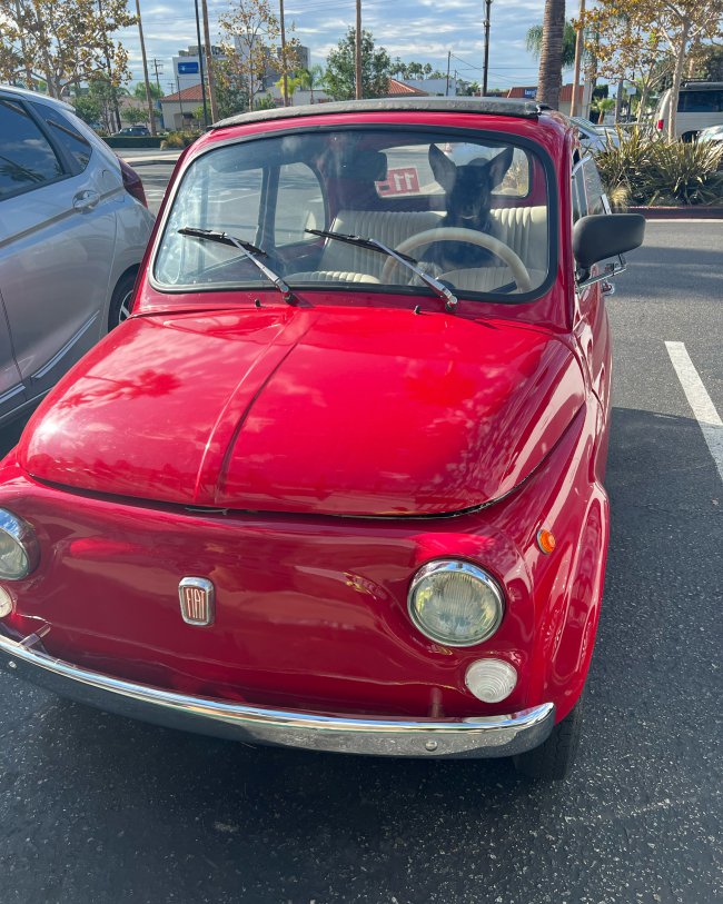
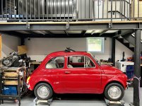
I have taken on the crazy task of trying to stuff a Ducati 1100 air cooled L-Twin engine in the back of my 1974 Fiat 500R, and solving all the challenges that will arise because of it!
It's been almost a year since my last update! A lot has been going on, but almost none of it Fiat related. I took a break from this project as we welcomed our first daughter last June. Now that we've gotten a bit into a rhythm, I've been able to give the Fiat more love!
Front Suspension
During my last updated, I was convinced that a prior repair job had resulted in an asymmetric suspension setup; however, upon further inspection, it appears that the chassis hard points are symmetric but the fenders are not. So I redesign the suspension, again, and I used this opportunity to lower the roll center, add more camber gain, and make some custom upper control arms using rod ends to give this suspension a lot of adjustment. I also now have access to a 3D printer so I was able to make some test parts to make sure I was happy with the alignment before building everything. I ended up adding adjustment to shift the wheel forward or rearward 1/4" (6mm) allowing me to better fill out the wheel well. Has anyone else felt that the front wheel should move rearward to better fill in the wheel well?

Still need to finish the cross brace supports, finalize the hardware, and probably add an anti-roll bar and a rebound stop (will just use the shocks for bump). The GAZ shocks are totally busted, leaking and not holding pressure, so that's disappointing. I might find a local shop to rebuild them (shipping back to the UK is not cheap), or look at switching to a different manufacturer. Also, it is worth noting that with this steering rack and brake upgrade, I do run into interference at full lock between the brake caliper and the upper control arm. The custom arms are designed to reduce this but it will still contact. Not sure if anyone else has run into this issue, but I'll look at modifying the rack to limit the travel so that this can't happen while driving.
Engine Frame
I ended up redesigning to engine frame, adjusting the position of the engine so I don't need a belt tensioner and modifying the frame so I have access to the engine bolts on either side of the rear panel. New parts were designed and printed to verify measurements on the engine and the Fiat's frame, then I had the tubes laser cut and routed out a tacking jig. Once I was happy with how everything fit, I welded it out and cross my fingers. It fit!

Overall, I'm pretty happy with this aesthetic of this frame and how it pays tribute to the classic Ducati trellis frames! I still need to finish welding out the frame, add the last engine mount, gusset everything, oh and build the rest of the engine frame, but this rear section, making sure everything lined up between Fiat's frame and the Ducati's engine mounts was the highest risk. Glad this all seems to fit up nicely.
Looking forward to what everyone thinks. More to come, with hopefully much less time before the next update!
Hey Everyone! I it's been about 3 months since my last update, and there has been some good progress, though not as much as I'd like (is it ever?). See below!
Front Suspension
Last time I realized that there had been some funky front end repair work that resulted in my suspension mounts being off. Upon further investigation, it does appear that the driver suspension points are shifted about 1/4" to the outside, when compared to the passenger. I tried to take this difference up with shimming and adjusting the control arms, but although I could get the static alignment correct, the camber changes were very different between the two sides. Also, I wasn't super happy with the design of those control arms and that they contact the support frame under full bump, SO, I've decided to make a new suspension mounting structure, lower control arms, and modify the upper control arms to fit the bigger tires with this messed up body.

I made asymmetric lower mounts to correct for the difference in mounting positions and to allow for lower and longer lower control arms, give me a better roll center height and camber control for the new wheel size. The lower structure is pretty simple, so I can remake that once I fix the suspension mounts.

Mounting the coil overs to the wheel well gave me some concern, so I built a test rig to see how much load I could put into the shock tower before yielding the structure. I got up to 800 lbF with less than .015" of deflection and decided it shouldn't be a problem keeping the stock structure as is without added re-enforcement. Also, the MrFiat coilovers didn't seem to be of the best quality and were limiting my total droop travel, so I ordered some GAZ shocks. Excited to see the difference!
I also finished up the steering, modification of the brake pedal for clearance, and added a spacer to the pedal assembly to give the master cylinder a bit more room.

Rear Chassis
I've decided to keep the front relatively mild from an upgrade perspective - using all standard off the self 126 parts and upgrades. I am making slight modifications to the control arms and mounting structure, but in general, it's in the spirit of the original car. The rear needs to be a totally different animal due to the engine packaging. This Fiat is going to be all business in the front, party in the back!
First, I cut out some of sheet metal that was going to interfere, like the rear suspension mounts, engine bay closeouts, rear engine mount and part of the air inlet snorkel thingy.

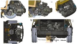
The Elite MX200 differential/reversing gearbox arrived so I built a simple jig to hold the engine and diff with respect to each other so I could put it in the car and make sure everything lined up the way I had hopped. As expected, I needed to change things around a bit to ensure I had acceptable CV angles, spacing between the engine and differential for the correct belt length, and to make sure I had good clearance to the engine lid (decided I want the option to keep the engine completely concealed)

After I was happy with the rough position of everything, it was time for another scan and to get heavy into the design work.

The frame needed to connect to the vehicle at 4 points: two forward lower swing arm mounts, and the two rear engine panel mounts. The frame not only needed to hold the engine, differential, and belt drive assembly, but it also needed to contain my suspension mounting locations, and look cool!
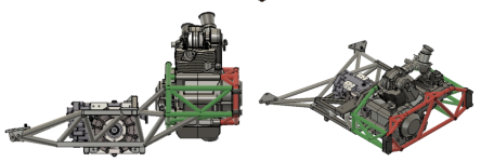
I started with the engine portion of the frame. With the motor being lifted from a Ducati, I wanted to retain the same "trellis" look of those bikes. I also wanted to have the option to run this car without the engine lid and panel, primarily help evacuate heat out of the engine bay during aggressive driving events, but also to look awesome. The frame is actually two parts (shown in green and red) that way the engine can actually be removed without cutting it out of the frame!

Next was to figure out the frame around the diff, and suspension pickup points. After doing some quick and dirty suspension sketches, I realized I could package a double wishbone suspension, which I used to set my nodal constraints. Then it was a matter of connecting the dots in a side/elevation view, then in bottom/top/plan view. I wanted to give the diff some adjustment since hitting the two drive axis will be extremely important, so I have incorporated slots and shims accordingly.

After I was fairly happy with that design, it was time to tie everything together, adjust, repeat! After quite a few iterations, I ended up with a design that I can make work. I've now ordered the laser jet sheet metal parts tubing so hopefully I can start fabricating next week!

In the meantime, I need to finish up the outboard suspension details (shock mounts, a-arms, uprights) and belt tensioner. That should be the main things to knock out before she can be back on her feet again!
Looking forward to hearing what everyone thinks and I promise to not let so much time go by before another update!
Attachments
Last edited:
Happy New Year! It's been a few weeks since my last update, so I figured I'd fill everyone in! Since I'm still waiting on the differential to come in, I have shifted focus to the front of the car.
Wheels and Tires (Tyres):
When I first started this project, I was planning to use early Miata suspension, since they are plentiful in the States, super cheap, and a good way to get better suspension, steering, brakes and hubs/cvs/axles that can handle the added power. Since I know people run 175/50R13s on these cars, and 13" wheels are the smallest you can fit on a Miata hub, I figured I'd throw on my buddy's 185/60R13 Miata wheels tires and see if this was possible.

Haha, absolutely not! At least not without massive modifications and I'm really trying to limit the amount of bodywork I do at this stage. Then I was curious to see how tight the 175/50R13s would be, thinking I could run 13s in the rear, allowing me to run Miata hubs that can support the power increase, and run 12" wheels up front if I still had clearance issues. I ordered a tire and checked the clearance.

Diameter looks okay, but they're just a little too wide to fit without doing any body work (or raising the suspension height). During this time, I also found out about the Fiat 500 CV/Tripod upgrade which seems to be good to handle the higher power applications, meaning I can stick with a 12" wheel option and be fine. I ordered a Yokohama A539 in 165/60R12 and was happy with the clearance at the rear. I also got some help from Ian, @Bleeding Knuckles, who runs these, boosting my confidence in selecting them. I can't seem to find any of these tire dimensions, so I just calculated the size, but note that there is more than a 10mm width differences between these two tires! Now that I know what wheels and tires, I can move onto the suspension.
Front Suspension
Forcing myself to stick with 12" wheels was really a blessing in disguise. It meant I can use off the shelf aftermarket parts, saving time from designing a front suspension. I bought this Mr. Fiat leaf spring conversion kit and started to install.
Unfortunately, the aluminum leaf spacer on the driver side was being stubborn. After a couple hours of hammering and a ton of heat, it finally came off, but not without damaging the mounting bolts, now loose and with damaged threads. I could see a broken tack weld on one of the existing bolts, so there had definitely been a repair in this car's previous life.

I cleaned up the threads with vice grips and a thread die and since I wasn't using the spacers any more, I cut notches in it to give access to tacking. This allowed me to make sure studs were normal to the surface and aligned to the other side. After tracking and grinding, I put some torque on them to make sure they won't come loose in the future.

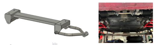
Now I was ready to bolt up the lower cross member but it turns out that the bolts were too far apart by about 1/4". Not the end of the world, nothing that can't be fixed by a band saw and a welder! I cut the member in half, bolted it up, aligned everything best I could, and tacked it in place. Since it had such a large gap, I took my time welding this up, trying to keep the part from getting too hot, and constantly checking to make sure the cross member didn't warp out of place. After it was all done, the part bolts up nicely. This will require some tricky alignment compromises, since my lower inboard balljoints are no longer centered on the vehicle, but I will be a future me problem. I'll likely go back and fix this when I revisit the body work down the road.

I also got the Mr Fiat front disc brake conversion and bolted those up, along with the upper control arms and the shocks, so I could take some measurements on the suspension.

I was happy with the geometry of this setup, especially compared to stock, but after playing around with the geometry in CAD, I realized it can really benefit from a higher inboard upper ball joint mount, resulting in much less camber change, a longer instant center, and therefore a lower roll center height. So, I'll probably also add these suspension relocation brackets, since it should help the suspension even more.

Brakes and Steering
For Brakes, I copied Jacques, @Bounding Bambino, setup and ordered a dual circuit Master Cylinder from a 128. It’s quite a bit longer than the stock cylinder, and requires different mounting holes. I hacked up the old mount, bolted everything together, then put some spacers between the assembly and the bulkhead. It still had minor contact, but I took care of that with sledge hammerNow it fits like a glove! I’ll make a nicer spacer for it later, but I’m happy with the overall fit.

I also decided to go with the 126 rack and pinion upgrade. This seemed like a no brainer since you just can't compete with the feel from a Rack and Pinion steering. I ordered the rack, the bracket kit, a double jointed column, and found a local 128 column to steal the steering shaft spline so I can adapt the stock 500 steering column. The bracket kit is pretty expensive and doesn't fit the rack very well, but it was nice to not have to make my own mounts. I mounted everything up, took a guess at where the shaft entered the bulkhead and drilled away! It was only slight off, nothing a little die grinding can't fix! I do remember Jacques mentioning that he had interference with this clutch pedal that requires modification, but I actually have interference with the brake pedal. Should be an easy mod to clear though.

And that's what's been going on the last few weeks! Near term items include:
I'm curious to hear what everyone thinks!
- Shock supports
- Check wheel clearance and hope there are no major issues
- Finish up steering connections
- Finish brakes and plumbing
- And many more!
-Bobby
Attachments
Hey Everyone - I wanted to give a quick Powertrain Update to go through my process of engine and differential selection!
Although I loved the idea of using the Ducati 1100 engine, I did look at a few other options including an electric motor and a much more powerful, water cooled Ducati 1098 engine. I even looked at a Moto Guzzi engine using a VW Beatle transaxle since Fiat had considered using Moto Guzzi on the 500s once upon a time, but that engine isn't very fast revving and I decided I really wanted sequential shifting! My first thought was to look at how these different options would make the car accelerate - so I made a "Tractive Force" plot, showing the vehicle's acceleration (in G) for a given speed in each gear. This is also a helpful tool for choosing my final drive.

I plotted the stock Fiat 500, just to remind myself of what I was comparing everything to. I was actually seriously considering an electric option similar to what Electric Classic Cars offer, but I decided it was going to be too slow for my liking. Maybe I can do a more custom electric option for a future Fiat 500 when I have more time to figure out how electrons work. The Ducati 1098 option would definitely be the fastest option of the bunch, but this power curve isn't nearly as smooth, and I really don't need the car to be that fast, even if I were to play with different gearing. Plus, I really didn't want to package a water-cooling system. The air-cooled Ducati 1100 seemed like the right balance between power and drivability. I'll need to add a couple of fans and open the rear of the car to get some good flow over the heads and oil cooler, but rejecting heat through oil coolers in the engine compartment should be much easier than rejecting heat through a radiator. This will be future me's problem.
Now that I've fixated on a particular engine, I need to figure out how I'm going to get this power to the ground, and ideally, go backwards. In the past, I've made a handful of chain-drive differentials but I no longer have access to free CNCs. You can buy complete chain diffs but they still require you to make custom diff mounts. These would also require a separate reverse solution, which I could solve with an electric motor or a reversing gearbox. I could also look at using a small differential from a car or ATV, but these options would just take up too much space, and since I'm trying to keep the back seat (a requirement from our dog, Peach), I really need to be space conscious. Below shows the Z-Car's solution - I'm trying to do the same in half the space!

So, I started looking for an off the shelf differential (not a spool rear end for dune buggies) that included a reverse. There seemed to be 2 players in this game: Quaife and Elite.
Quaife is a good brand, I've used their diffs before, and they have a pretty smart design that doesn't really need to be serviced; however, with this configuration, the engine needs to be mounted in-line with the diff, as it would be in the motorcycle. There are lots of these units out in the wild, including the Z-Car and my buddy's Fiat, but they all have much more space available. To package this, I'd have to run the diff in front of the engine, and squeeze everything together to give me as equal length axles as possible, reducing CV angls, while still fitting the engine in the car. This configuration gives me lots of room in the engine bay but it wouldn't be the most aesthetically appealing to me as it hides the engine’s exposed belts and dry clutch. It also would be more challenging to package a symmetric rear suspension.

Elite is a brand I've never heard of, and can't find a ton of information on, but they use a tried-and-true clutch pack style differential. I would eventually need to service this unit, but I don't expect that I'll put enough miles on it for this to be an issue. What's unique about this differential is it requires the engine to be mounted in a transverse orientation. This would allow me to directly mount the engine to the diff, eliminating the need to run a chain or belt, as required with the Quaife. However, after thinking about the critical alignment between the two units, and how low I'd have to put the engine in the car to line up with the diff, I thought an indirect drive solution would be best. It also allows me to reduce the input torque as seen by the differential, something that was a concern from the manufacturer.

I started to weigh the pros and cons of each solution, moving things around in CAD to see what packaged the best, making some wood templates to check fit and even buying a blown motor to put in the car and see what would actually work. After a pseudo–Design Review with my buddies, we decided that the Elite differential gave me the most options, packaged the best (especially from a chassis design side) and would deliver on the aesthetics potential of the engine bay.

So, there you go, I ordered the Elite option, which should hopefully arrive in January. In the meantime, I can focus on the front suspension, tearing down the donor bike, and designing the rear frame!
For the next update, I'll talk about wheels, tires, and front suspension stuff. I'm looking forward to hearing everyone's thoughts and continuing to get lots of help on this project!
-Bobby
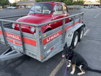
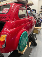
Before I started teardown, I needed to make a cart for the car. This would allow me to move the body around the garage and elevate the car enough to work under. However, I couldn't go too tall, or I wouldn't be able to get the car under the mezzanine. After a few measurements, I ordered some Amazon bits, picked up some steel, and whipped up this little guy.

I measured corner-weights with and without me so I would have a good baseline for the project and something to keep in mind as I was adding and removing components. Then it was time to lift the car onto the cart, which totally was not sketchy or scary at all.


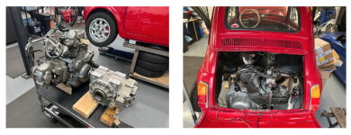
With Francesca on her new set of legs, it was time to remove the engine and suspension


With all the major components out of the way, I had a buddy come over to 3D scan the engine compartment so I could start trying to figure out how I would package the motor.


Now the design work can begin!