Technical 2002 Ducato fuel gauge module?

Currently reading:
Technical 2002 Ducato fuel gauge module?

Ronnie63

Member
Joined
Dec 27, 2020
Messages
111
Points
86
Been having trouble with my fuel gauge suddenly dropping to empty or never coming on from the start! been through everything and narrowed it down to the vibration damper module, I have had this apart and re soldered every component on the board but the gauge still randomly fails?

I can't find this module anywhere, so if anyone knows of or has one please let me know?

Thanks Ronnie
 

Attachments

  • s-l1600.jpg
    s-l1600.jpg
    162.4 KB · Views: 359
Hi Ronnie,

There are old threads on this forum which relate to this problem, and which can be found via the search function.

There is also the attached a thread on the Motor Home Owners organisation (MHO), which suggests that the problem may be due to a fault at the connector.

From your picture and the one on the linked site, there were two different versions of the device. I have seen a posting, which suggests that they may not be interchangeable.

I am sorry that I cannot help further.

https://www.motorhomeowners.org/pos...ingfix-6882130?trail=&highlight=fuel+gauge#21


Thanks once again for responding to one of my posts. I think I read that post and on that basis I removed the plug and hard soldered the wires to the pcb but used bullet connectors should I need to remove it.

I even tried to source the smd micro chip that's inside the module but could not find one!

Thanks Ronnie
 
Still no further forward with this! I can't find a module anywhere, I'm thinking this box controls the gauge the red low fuel light and then flashing red desperation light. I wonder if the box could be bypassed to simply show the gauge reading?

I did however find this foreign site for a module? Looking at the pictures you can see the smd chip that I think might be dedicated or pre programmed?


https://www.arciricambi.com/store/c...lo-serbatoio-fiat-panda-ducato-originale.html

I'm open to any options at this point?

Thanks Ronnie
 
Hi Ronnie63

I fear I may be simply telling you things you already know, but here goes !

The damper module is primarily to stop the fuel gauge bouncing up and down as the fuel sloshes around with vehicle motion. I guess they have also included the driver for the steady/flashing warning light.

The module in your photo seems to be made by Magneti Marelli, and the chip by ST Microelectronics. This could well have been an OEM only part, and almost certainly obsolete. I doubt if it is a programmable part. Do you have the part number(s) of the chip fitted in your own module ?

It's possible that you could connect the sender more directly to the gauge, if you can identify the relevant wires and are prepared to put up with a bouncing needle. It might be prudent to do some measurements first, e.g. the resistance of the sender, how it is fed with power, and what sort of signal the gauge expects to see. I can maybe then suggest a simple interface circuit, but no promises !
 
Hi Anthony, thanks for your input, I did notice when I unplugged the sender unit the gauge remained where it was, meaning it was not a live reading so maybe the module read the gauge at set intervals?

The markings on the ST chip are B99040138 and L91900

I dont fancy removing the sender to measure it's top and bottom resistance! The unit incorperates the fuel lift pump as it's a common rail engine, the bouncing needle would be a pain! But unless I can source that chip I'm stuck! I can deal with SMD soldering, I could replace the through hole capacitor and 2 diodes but that might be a waste of time lol.

Thanks Ronnie
 
Hi Ronnie 63,

Is it possible that the device includes a stepper motor driver? I do not know when stepper motors where first used on the Ducato for analogue indications, but my 2006 x244 uses them. Use of stepper motors would explain your gauge not returning to zero when disconnected, and the multi lead IC. Stepper motors are inclined to stick on laid up vehicles. See thread by ducatiman, which is currently linked on Ducato home page.

Thanks Communicator.

I have no idea on the stepper motor, would it live within the fuel tank? I can't find that thread you mentioned, is it on this forum?

Thanks Ronnie
 
sorry I found that post relating to speedo movement, so stepper moving the needle.

Im my case the gauge can be correct and then slowly start to fall until it hits empty, other times it can be reading correctly at say half a tank but the red light is on or it could be flashing.

I noticed when I had it all stripped down and when the gauge went faulty re plugging the module mostly made it work again.

Another idea was to find the +ve to the module and fit a switch inline which might reset it should it play up in the meantime?
 
Hi Ronnie 63

I had initially assumed that your vehicle was too old to use a stepper motor type gauge, but I am beginning to think this is the case. The IC in the module probably therefore also contains the necessary sections to send the appropriate pulses to the meter. I have failed to find any reference to this IC in the ST back catalogue, so it was probably specially developed and not released to the open market. The later "white" modules like this also seem to be unobtainable now even from vehicle breakers.


In general, the most unreliable things in electronics are connectors / switches which corrode and tarnish. Solder joints are also sometimes problematic depending on how well they were made in the first place. Semiconductors (IC's, diodes, transistors etc) are normally pretty reliable unless they have been gives a surge overload or a large static discharge, neither of which seem likely.

There is one other part which I haven't mentioned above. On the photo of the PCB is a large electrolytic capacitor, it looks to have a value of 470 microfarads but I can't see the voltage rating. This type of capacitor is known to "dry out" internally over the years and lose capacitance. Many a PC motherboard has succumbed to this effect. It's a long shot, but as you have nothing to lose I'd suggest you try renewing this component. There is a chance that it could all come good - fingers crossed !
 
Hi Anthony, thanks again, I did hard wire the connector and fit bullet crimps so it can be removed to rule out connection issue. I also reflowed every solder pad on the pcb, but the electro cap is probably a good shout, I have a large amount of those readily available, will give it a go and report back

Thanks Ronnie
 
I just fitted a new 470uf 25v capacitor, from the get go it failed to register! I did however fit a discreet switch to the 12v feed of the module, switching the 12v off causes the gauge to rise to almost full then fall and fade out, putting power back restores a reading.
Of the 5 wires to the module 2 are +12v 1 is +5v 1 ground wire the other seems to sit about +2v

Thanks Ronnie
 
Hi Ronnie,

With only five wires connecting to the module, my stepper motor idea is a non starter. The module will have to have an analogue output. As a guess I suggest the following functions will have to apply to the connecting wires, but in what order? 12V+ supply, earth, input from tank unit, output to gauge, and output to warning light.

To aid understanding the problem, perhaps it will help to list the functions of the device. All of my suggestions stand open to comment.

1. Smooth an input signal which varies due to the fuel sloshing in the tank.
2. At an output of approximately, 25% maximum provide output for the low level light.
3. At about 10% of maximum reading change low level light to flashing.

As a last resort, it may be possible to re-engineer function 1. above, perhaps by using an operational amplifier with a capacitor in the feedback loop. (Further investigation required.) However that may not be worth the effort, and you may wish to stick with your simple switch.

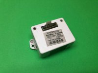
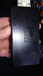
There are pictures of a different OEM unit, performing a similar function to yours, attached to a posting on the Motor Home Owners forum. The poster does not completely identify the base vehicle, as it could be a 2.8 idTD. See following link for pictures, but the unit linked to by you, would seem to also have been fitted to earlier vehicles.

https://www.motorhomeowners.org/post/fuel-gauge-not-workingfix-6882130?highlight=ducato+fuel+gauge
 
Last edited:
Thanks Communicator, had a read through that thread, not sure what to do next? Not used the motorhome yet since fitting the button, will see how well it works when using the van and think on the next step.


Cheers Ronnie
 
Not long completed a 850 mile trip and the gauge never failed! It does not register a full tank when filled, it sits one notch below full, Before we set off the gauge played up but using my switch reset it for the whole trip, weird!

Thanks Ronnie
 
Hi
Some observations on your fuel module issue which may help.

I wonder if you have misread the ic part number, I can see a few pictures of ST L9190D on google, but nothing for L91900. Unfortunately, I cant see a data sheet anywhere.

I would guess part of the circuit is a low pass filter with a long time constant, going by the rate at which the fuel gauge needle typically moves. The large capacitor could be part of this circuit? Have you checked whether the capacitor shows sign of venting (the top bulging, trying to open up the stamped cross).

My van is a 2000 2.8 dti and has had problems with the fuel gauge reading. However, it has a black module with 6 wires (photo attached). I would guess the functionality may be the same but the black module circuit uses through hole components and a DIL ic. (Unfortunately, I did not record the IC number when I was reflowing the solders joints). Could the white module be replaced by a black module?

Just fyi, it appears ( I hope) that my problem stemmed from the female contacts making a poor connection with the male inside the connector. I removed each female contact and V. Gently nipped them up to make a tighter contact. However I am still in the testing stage of my fix, I've yet to get through a tank of fuel to see how it goes.

Regards

Mark
 

Attachments

  • IMG_20210916_120749.jpg
    IMG_20210916_120749.jpg
    2.2 MB · Views: 52
Hi
Some observations on your fuel module issue which may help.

I wonder if you have misread the ic part number, I can see a few pictures of ST L9190D on google, but nothing for L91900. Unfortunately, I cant see a data sheet anywhere.

I would guess part of the circuit is a low pass filter with a long time constant, going by the rate at which the fuel gauge needle typically moves. The large capacitor could be part of this circuit? Have you checked whether the capacitor shows sign of venting (the top bulging, trying to open up the stamped cross).

My van is a 2000 2.8 dti and has had problems with the fuel gauge reading. However, it has a black module with 6 wires (photo attached). I would guess the functionality may be the same but the black module circuit uses through hole components and a DIL ic. (Unfortunately, I did not record the IC number when I was reflowing the solders joints). Could the white module be replaced by a black module?

Just fyi, it appears ( I hope) that my problem stemmed from the female contacts making a poor connection with the male inside the connector. I removed each female contact and V. Gently nipped them up to make a tighter contact. However I am still in the testing stage of my fix, I've yet to get through a tank of fuel to see how it goes.

Regards

Mark
Did you get to the bottom of this problem I have the same module as you in the picture. I'm having similar issues with my fuel gauge...
 
Did you get to the bottom of this problem I have the same module as you in the picture. I'm having similar issues with my fuel gauge...

Thanks guys, no the issue is not resolved, the capacitor was replaced and the old one had not vented or bulged, the switch I added to the 12v feed to the module seems to work in getting the gauige to register but it can be a faf!

Thanks Ronnie
 
Hi
I don't want to tempt fate but since I nipped up the connector contacts the fuel gauge has been reading normally. Reflowing the solder joints didn't fix the problem. It has taken me a while to understand what reading normal is on my van because it has a long range tank (130L or so) and it seems the gauge only reads up to 70L of a normal tank, so the gauge sits at full until the fuel drops to 70L, then reads normally.

I aso applied a little contact grease on the connector to reduce oxidisation.

Regards
 
Back
Top