Technical Duato X244 cruise control retrofit- VICTORY!

Currently reading:
Technical Duato X244 cruise control retrofit- VICTORY!

Ocwobio

Established member
Joined
Sep 29, 2013
Messages
446
Points
172
Well, after 3 days of on/off toil, much aggravation, bad language and more- we are done fitting the Alfa 147 cruise control stalk; and it works perfectly!

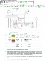
The main thing to do is check for the wires from the ECU that come to the black connector D018A (the much talked about black connector) under the left side parcel shelf/dash (on a RHD vehicle). There should be 6 wires into it from the engine bay, a thick red and 5 thin ones. IIRC (but see pic) one is pink/green, and I can't remember the others (loads of info online and here) and I have a diagram IIRC but the yellow/black, one is not one of them, leave that alone, nor is the thick red one. I believe that will only be there if the vehicle has aircon.

4 of the 5 cruise stalk wires excluding the yellow connect into the 4 on D018A as seen in my pic- this is just to illustrate the connections, connecting themas per the Italian diagram below- watch the mating of one colour toanother as they do NOt match, I pushed the stalk wires into the black connector to see how well they fit/could they be reused? Short answer, they fit Ok but are hard to put in place so I had a plan B. Then you will need the wires extended across to the the steering column, whether left or right. I used spare 7 core trailer wire as I had some, if 13 core trailer wire is used, so much the better as it contains an orange one that is not in the 7 core and you can match stalk wire colours 100%. I had to sub the brown for the orange, and not forget I had done so.

I chopped the thin wires where they entered the black connector and used an ex PC 4 way Molex connector as the pins were easy to extract with the correct tools and it will handle the current OK. This was soldered to the thin wires, extending them a little to make more slack to work with. Things are tight!

From the output of the Molex, the 4 wires via the 7 core were passed under and behind the heater controls/map bin, above the pedals- beware steering column rotation and secure well from pedal interference! Then up to top of column, with lower cover removed.

I originally cut the pins off the stalk wires after removing from the plug, but ended soldering them back on. I had some terminal connectors from a superseal type 6 way plug and socket, the female terminals fit the Alfa pins 100%. I believe the are Delphi GT150 female and are available to buy seperately. After soldering them onto the relevant connectors on my 7 way, I covered them with heatshrink and could then plug them onto the Alfs pins on the stalk wires, which I had meanwhile placed back in its original plug. Note that the yellow is not connected to anything at this stage.

We then need an ignition switched 12v supply for the yellow stalk cable. This is taken from the blue/green wire to the brake light switch, via pin 3 of the brake switch (blue wire) then on to join the yellow stalk switch by whatever means/routes connection method you choose. You will also need a 4 pin brake light switch- this is a cow to remove (see my other post) and you may find your brake switch already has 4 wires into it like mine had, but this does not mean the switch has 4 terminasl in it!

Fortunately between my brake switch and the main loom, there was a 6 inch piece with connectors each end which could be taken out-with difficulty!!- and worked on comfortably while soldering on the wire to bridge pin 4 and 3, and make the extension to the yellow stalk control rather than try it at the actual switch terminals.

This yellow wire from brake switch 4 via pin 3 goes ultimately to the yellow wire on the cruise stalk giving such a 12v feed. the remaining 2 brake switch wires- pins 1 and 3 are normally closed with brake off, and provide a signal path to the ECU when cruise is engaged, that the brake is OFF and can engage. Pressing the brake pedal signals cruise to temporarily disable. BTW, when replacing brake light switch for a 4 pin one, make sure the switch body is the correct length, and vitally that the operating tit is the same length as the old one, comparing both when off the vehicle.

These bad access hurdles surpassed, and connections made and new brake switch in and working, it remains to mount the Alfa stalk and it will be self explanatory after looking at the parts. Some trimming of the stalk
may be needed where a mounting hole we can't ue may need cutting off.

Very carefully check and recheck all the connections are correct- I had 2 wires in the Molex at the black connector end reversed, easy to rectify. Make sure there are no shorts (you did disconnect the battery didn't you?) and try it out.

The green dash light did not come on immediately on mine and others reprt the same. It took about 15 minutes with random switch ons and offs. as I had multiecuscan, I had connected to the systems with this on first key on, as there is a force relearn facility for after doing just this mod. I did not need to do that, and all parameters and indications logged as operating correctly first time, and responded correctly to control inputs.
Icould do tis joba agin in less time, but would not relish it. It's done now, and a road test proved all was most satisfactory in all aspects. RESULT!

Pics below in no real order......DOH! DSCN0986.JPG

DSCN0979.JPG

DSCN0994.JPG

DSCN0996.JPG

DSCN0997.JPG

DSCN0998.JPG

DSCN1002.JPG
 

Attachments

  • cruise diag 2.PNG
    cruise diag 2.PNG
    169.7 KB · Views: 980
Last edited:
I have beeen thinking about this install, and comparing it to the one in my Grand Espace. That has the same buttons to control it and the on/off switch too of course. However, on that it also has an extra button, that when operated, will temporarily disable (pause) the cruise until 'resume' is pressed. I find it really handy if, say the traffic thickens up for a while, or I find some other short delay or catching up to traffic, or the general flow is a bit up and down speed wise. This pause has the same effect as touching the brake pedal. So, on the Ducato install, as I don't have this pause facility and either need to brake slightly or switch it off completely then re-start and set speed again, I am thinking I shall put a switch in to allow pausing it. I reckon that if I put a push button switch- NC contacts- in series with brake light switch pin 1 and wherever it goes to, this will add the function by replicating a brake application and allow 'resuming' after pressing it and not having to start from scratch again. It will not affect the brake lights as they are on pins 2 and 4, and if I attach it before switch pin 3, it will cut the power to the cruise and it will need starting /turning on and setting again. It will be a while before I get round to it, but does anyone see any problems with the plan? Apart from yet more wires and the trials of getting them in neatly.
 
Last edited:
Ocwobio,

I understand your idea. However as you suggest the implementation could be rather fiddly. If you decide to proceed, I recommend confining the alterations to pins 3 & 4 of the brake pedal switch. You would have to cut the loop that you have made between pins 3 & 4, connect pin 4 directly to the yellow wire of the Alfa stalk, and loop to one side of your new push button. The other side of the button would have to be wired back to pin 3 of the brake pedal switch.

The main problems that I can envisage, are push button location and aesthetics. On you espace you currently have a dedicated button associated with the cruise controls, and importantly easy to locate and access. This would not be easy to replicate with the Alpha stalk.

A separate button could perhaps be mounted on the dash or steering column cover, but it would have to be in an easily accessible location, otherwise you could be pressing the brake pedal instead.


Sourcing a visually acceptable, normally closed push button, could be problematical.
 
Yep, aesthetics is a factor for sure. It will be a while before the trauma from the install fades enough anyway! BTW, the cruise switch on my Espace is in a horrible position, it was bad enough in my 05, down near the start button, but now on the later ones they've moved it to down under the parking brake handle, below my right knee, with 2 other switches, no chance of finding and switching it by feel, that's for sure. Maybe I ought to be moving that one instead.... I am going to get a new brake switch connector sub-loom length, and make hopefully a neat and tidy job whilst on the bench. The current one looks untidy, but does work well. Cheers for the input, as ever.
 
Last edited:
Well done Ocwobio. good to see you got there in the end. I totally forgot about your post!
 
Eh, I'm used to being forgotten about! In retrospect, if the black plug has the wires from the ECU, it's really quite simple, now I know how. And it works as it should, too. Glad I took the plunge. Now all that remains is to trim the lower column shroud to fit and put it back on. I have yet another mod I've thought out, relatively easy, when I can be bothered! Thanx for all your help in this mate. Cheers!
 
Gday Mate.
Very cool!


What is required to do this?
Trying to understand the full process...not just the wiring.


You buy an alpha stalk?
How much did this cost?
Then you have to wire up additional wires manually .

What is the total cost of parts without the labour?


To fit, do you remove old stalk...by disabling airbag, yank steering wheel, then removing old indicator stalk on left hand side from the combo switch?
 
Gday Mate.
Very cool!

What is required to do this?
Trying to understand the full process...not just the wiring.


You buy an alpha stalk?
How much did this cost?
Then you have to wire up additional wires manually .

What is the total cost of parts without the labour?

To fit, do you remove old stalk...by disabling airbag, yank steering wheel, then removing old indicator stalk on left hand side from the combo switch?

Great install :)

The only comment I would make Ocwobio

You mention needing to tap the brake to disengage the cruise.. does the clutch pedal not have a sensor?( or provision for one)

The Alfa 147 that donated the stalk is now @15 years old.. so plenty being broken
Part should not be expensive ;)

Charlie
 
Last edited:
Hi Charlie,,, regarding this,,,
The Alfa stalk control was not particularly cheap from a breaker here in the UK, or ebay. But, I did find one on ebay, an individual seller (not a dealer/scrappie) was parting out their car. I also had an ebay voucher, so the part net cost $0 (don't have pound sign on keyboard here!). They should be pretty cheap, if someone is also parting their car out.

If you find one, you can post on here with a picture if you like, or send me a PM, and I can verify the correct one. The labour cost was obviously 0 too as I did all the grunt work myself. All other materials were about 2m of multicore cable, (I used trailer wire as I have some), and an old molex connector from a PC wiring loom. It is hard to change the brake switch, as room below is limited, and access to get the old switch out is made difficult because of the way the steel dash frame seems to be built around it. I have a way, it is a bit brutal, and it is easier to actually do than explain, maybe. I needed to force the switch to a point it felt like it may break, but it did not, and I had to remove and replace it a few times afterwards to tidy up, and it was much easier when I knew how. Communicator had the same problem but IIRC found a different way round it involving grinding or filing the metal. If I had to do that, I would have given up, so I got angry and bingo! I found a way.

I took limited pictures, and no video, of the job as it was too difficult to do that as well, but I could do it again if I had to- obviously not enjoyable, but possible, lol! I was going to do another alteration to enable the cruise to suspend rather than disengage/ have to turn off, on and reset speed; I have not done so and with lockdown etc. it is not worth it. I also have no access to the vehicle at this time, for this reason. When it will be over, who knows?

I spent 3 days doing mine, because I had the time to do so, so could take a break when I had had enough! The most important thing is finding out if you have the wiring plug already connected to the ECU. What is your exact make and model, and is it left or right drive? I guess a determined effort could do the job in a day or less. A little soldering and some heat shrink needed. too. If I had needed to connect wires to the ECU that were not already under the dash, I also would not have done so either, just a step too far for me!

The worst bit, was tapping into the brake light wiring, as the connectors were very tight, access was poor, but I got a break when I noticed that there was a short section of wiring that could be unplugged and worked on seated normally- so much easier! I already had 4 wires to my brake switch, (there is a clutch switch already fitted on mine, but IIRC it does not need to be there for the cruise control to work I think ), but the brake switch only had 2 contacts inside it anyway. So had to be changed for the 4 contact one, about 10 quid or less.I found the plunger on this new switch was too long, but I was able to shorten it by breaking off the rounded end. This made it equal to the old one.

There are quite a few screws to remove the dash panels to access the wiring, on the left side (my vehicle is righ side drive), also the panel under the steering wheel. No issues with the airbag as I did mine with the wheel still in place.

If you do have a go at this, I will help all I can if you need it, sometimes it's hard via email/forum, and hands on is way better, but not possible, even if you were local, at this time! ( I am in south Cheshire/UK). Any other questions, just ask. Communicators' link to the Italian site was helpful,, I had to dig a little to understand it, but now I have done it, it is all crystal clear. You will feel like a hero when it is done and working- go have some beers! I did!! It was not necessary to use Multiecuscan to enable the cruise, on this one, but there is a facility to use it for that if it does need it. I just verified the control operation and switches etc. with it before driving. Bset regards my friend! Stay well!!
 
Last edited:
For those who may be interested, I will try to attach a pdf version of a modified eLearn diagram E5060, which shows the cruise control as I installed it. I have been politely descibed as fastidious, which is probably correct, as I like wiring to be tidy where possible.

Points to Note.

1. In line with the above I took the cruise control supply from The designated fuse F27, by bridging from connector D160A/6 to D160A/1, adding a new wire from D160A/1 to the new switch stalk. D160A was hard to locate, as it is concealed under framework, under the instrument binnacle. Also there is not much slack in the cableform.

2. The other additional wires are the four from D018B.
3. I removed the original connector from the Allfa 147 stalk and used a 6 way 2.8mm mini connector to connect to my wiring.


The four 0.5mm wires to connector D018B were pulled into 6mm PVC sleeving and routed with existing cableforms behind the radio. The single wire from D160A was treated in a similar way.

As Ocwobio has stated, changing the brake pedal switch was not easy.

The Alpha 147 cruise control stalk has a conical upper bracket, and a rectangular lower bracket. I carefully sawed off part of the conical bracket, as it interfered with the Ducato switch unit. The lower bracket fitted into an existing recess on Ducato unit. Rather than rely on single fixing point, I added a simple metal tie at the bottom corner of the two switches.


Cutting a matching slot in the lower steering column cover to accept the cruise control stalk requires considerable care and patience.


The outstanding task is to have another try at getting connector male inserts into the mating half of D018B. No success so far, but as my vehicle does not have aircon, not a serious problem. Current arrangement is heath robinson, but physically, and electrically secure.

As regards Ocwobio's proposal for a suspend button, there are two problems. Firstly space to mount such a button. A possible locaton location would be adjacent to the top RH corner of the gear lever glove.
Secondly there is the availability of a suitable NC push button. I was looking for a 16mm black NC button. All aesthetically acceptable buttons were NO, and as such would require an inverting circuit. This could be as simple as a small (e,g, 5W 12V) incandescent bulb in series with the pedal switch, with the PB connected to earth the common point. There are however some stainless steel 16mm SPDT buttons on eBay, which may not be too long behind the dash. I have also designed a relay circuit which could make the existing Resume button dual purpose. This developement is more complex than the current modification, and has been placed on hold. However it is tempting due to its operational simplicity.
 
Last edited:
I’m really inspired by all your hard work and information, thank you for posting, I’ve been reading the updates avidly. I too have an 05 X244 with air con and RHD. I’ve sourced the Alfa cruise control stalk, but don’t have the skills or confidence to proceed...
 
Great install :)

The only comment I would make Ocwobio

You mention needing to tap the brake to disengage the cruise.. does the clutch pedal not have a sensor?( or provision for one)

The Alfa 147 that donated the stalk is now @15 years old.. so plenty being broken
Part should not be expensive ;)

Charlie
Hi Charlie,,, yes it does have a clutch switch, but it was fitted from new. Don't know if it plays a part in CC operation,think I tried it once and engine raced, but Cc remained active. I THINK! I can't remeber now, not really something sensible to try again, methinks. It's no hardship to tap the brake and get temporary pause, I guess, so I'm leavingit as it is for now.
 
Gday Mate.
Very cool!


What is required to do this?
Trying to understand the full process...not just the wiring.


You buy an alpha stalk?
How much did this cost?
Then you have to wire up additional wires manually .

What is the total cost of parts without the labour?


To fit, do you remove old stalk...by disabling airbag, yank steering wheel, then removing old indicator stalk on left hand side from the combo switch?
Hi,,the cost all depends on how much you pay for the stalk.
You only really need about 2m of muticore wire, some solder, heatshrink,new brake switch if yours is not 4 pin type, and about 1m of single wire,
time is cheap if it's your own LoL, and no need to remove steering wheel, so no airbag issues. Disconnect battery neg first tho. Stalk does not replace anything, it is in addition to the indicator stalk. Parts spend for me was below 50 quid, ebaay voucher paid for all of it that I didn't already have (y) Be aware that not all Alfa stalks will have te same coloured wires, but as long as you note the pin numbers it doesn't matter I guess. If buying used, try to get the seller to cut the wires below the plug,nearer to the main wiring, that way you can save some aggro making connectors fit the stalk plug, by just joining the wires by solder and heatshrink.
 
Hi guys. New on this forum. Here because I am trying to install cruise control on my Peugeot Boxer 2.8 jtb 2005.
I followed all steps from this topic and managed to get the cruise control recognized by the ECU! I can see all functions working via MultiEcuScanner. So far great succes.

However I just took a 12v for testing purposes, so not via the brake switch at the moment.
But I cannot get the CC to engage, because Multiecuscan says it is blocked because of the brake switch. I also see a code p0703, which indicates a faulty brake switch.
But before I activated, there was no error, after CC activation, this error occured.

In the original Electric plan, you need to get run a wire from pin 1 on D160 towards the CC stack. I do not have that yet.

Is the ECU now expecting this brake light (I030 NC) loop to be closed via the CC stack since I installed the CC?

Many thanks in advance
 
Hi Max,

1. Do you have the two pole (black and white?) brake light switch fitted? The body colour of the original switch is all white. It does have four wires to it, but two are not connected at the switch.

2. For ease of access, you do not need to connect to D160A, as shown on the eLearn diagram E6060. Most contributors seem to choose to make the connections at the brake light switch.

3. You need to make the connection from the yellow wire of the Alfa stalk to either D160A/1, or to the blue wire at the brake light switch.

4. The 12V supply can be taken from either fuse F27 (cruise control) by bridging D160A/1 to D160A/6, or more easily from fuse F26 (brake lights) by bridging the blue and blue/green wires (pins 3 & 4) at the brake light switch. Please be warned that the pin numbers on the eLearn digrams do NOT match those moulded onto the 4 way connector that plugs into the switch. (Bad drawing practice on eLearn, which is nothing new!)

I am attaching a copy of eLearn drawing E6060, which I have amended for my own records.
 

Attachments

  • Cruise Control 5060 Mod.pdf
    431.5 KB · Views: 169
Hi,

Many thanks for the reply, it states indeed what I still need to do.
1. I have the white switch with 4 wires to it. So i guess it is not the 4 pole switch, will check it. I assumed that because 4 wires to it means 4 pole, unfortunately not...

2/3. Indeed that is a lot easier

4. That I totally forgot... did not know the elearn was wrong.

Thanks for the pdf, clears things up! Will continue when I have sourced the 4 pole switch , black one right?
 
Back
Top