Technical X244 brake light switch, it's a bitch!

Currently reading:
Technical X244 brake light switch, it's a bitch!

Ocwobio

Established member
Joined
Sep 29, 2013
Messages
446
Points
172
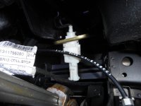
How the hell can I change the brake light switch?? There is no room to get it out, once the bayonet action has been done. It is easy to disengage the lugs, as its only a 1/4 turn, but it is completely impossible to pull the switch away from the mounting plate. Even the wiring plug can't be removed, as there simply is not room. If the plug could be taken out, the switch body would be easy. But its all solid steel all around the bloody thing. There is no room at all so short of smashing the old one to bits, (which would still leave the replacement impossible for all the same reasons), what can be done?

This is a real PITFA! Has onyone done it? This is a major, but MAJOR design fault.

Nurse! Medication!!:cry:
 

Attachments

  • DSCN0974.JPG
    DSCN0974.JPG
    4.1 MB · Views: 485
Last edited:
When I read this I thought it rang a bell somewhere in what used to be my brain and couldn't bring it to mind
Then I read the next thread that I posted sometime ago and the penny dropped.

As in my thread it was the fuse that had been overloaded and luckily I did not have to remove the stupidly located switch.


Best of luck.

:cool:
 
I'm not so lucky. I do not have problems with the brake lights, they work as they should. I need to replace the switch with the correct one for cruise control operation, that is take out the 2 pin and replace with a 4 pin one. Only way I can see is risk seperating the sub assemblies of the switch, and take out one piece at a time, and vice versa to put the new one in. Not a sensible thing to do, as springs and contacts will likely fly all over, and there is a risk damge will be done or it may not work afterwards.
 
I am new to this forum, but prior to joining I had carried out the modifications outlined in this thread.

Perhaps you did not receive my PM?

My answer to the brake light switch problem was to partly release the switch as you have done, and then file a slot about 3 to 4mm deep in the bracket above rear of the switch. (In the interests of structural integrity keep a radius in the corners.) After removing the connector the slot may be enlarged with slightly less difficulty. Also I trimmed about 1mm from the upper flange of the connector, using small side cutters.

The metal to be filed seems to be a stiffening bracket, and part of the steering column support. The steel could be high tensile and work hardened at the edges by shearing during manufacture, anyway filing seemed easier once I got through the edge.


I recommend using eye protection.

If your vehicle is similar to mine (2006 x244) I do not think that removing the switch support bracket is feasable, as it seems to be fixed to the pedal bracket with four pop rivets. The upper two are impossible to reach. That meant that the remaing option was to attempt partial removal of the pedal assembly. Filing the slot seemed the least traumatic option.
 
For completeness, I should have added that I found, and eagerly followed the following link on eLearn.

"Op 5550D10 BRAKE LIGHT SWITCH R&R"

The response was "Operation not available."
 
For completeness, I should have added that I found, and eagerly followed the following link on eLearn.

"Op 5550D10 BRAKE LIGHT SWITCH R&R"

The response was "Operation not available."
I need not comment, lol!

Its a ridiculous state of affairs, really. The 'everlasting brake switch'- it better be in view of the foregoing. I have to work upside down, wrong handed and no room to swing a file, so thought that I would have to bend the bracket down, remove and replace switch, bend bracket back. Trying to find how many and where are the screws that hold on the lower dash panel, and what needs to be removed before it, but my manual is lacking in some pages and much detail. I can't work directly in front of the area as there is stuff below the seat, so even if seat was removed access is still apalling.

Maybe it would be easier to use the current brake light wires to operate a relay to simulate the NC contacts that I need to acquire with the 4 pin brake switch. What a ballache!:bang::bang:

Didn't get a PM btw, but no probs.
 
This could be considered a safety critical application, in that you need to disengage the cruise control as soon a you press the brake pedal. Best to stick with the switch if at all possible.
 
I get it. But a relay will not impede the safe operation of the brake control. Switching time is the only factor, which will be mere milliseconds. I may yet look at picking the feeds I need up somewhere else, or going in series with the clutch switch; in which case either/or switch will carry out the required signal. But FFS! What were Fiat thinking/smoking/drinking when they came up wi' this? Answers on a postacard to- Dat Crazy Guy, c/o The Loony Bin, Bedlam rd., Nutbury.
 
I was thinking of relay coil failure, rather than timing. To cover that possibility, you could use two relays. One with the coil across the switch, using NO contact and the other in parallel with the stop lamps using NC contact, both contacts in series. However I think that arrangement is rather too complicated.
 
Last edited:
Regarding the cause of the problem, I am tempted to speculate that it could simply be the adoption of the adaptor lead. The socket on this lead has a chefs hat sort of shape. It is the rim that will not pass through the slot. This rim is not present on the original harness connector. Another possibility is a design change involving lowering of the obstructing cross member, without fully appreciating the implications.
 
I think you are a bit off the track here,there is no slot. If there was, I'd be all over it as a possible escape route. I'm not going to put 2 relays in, that would be silly IMHO, all I need is a + ignition switched feed that goes away when the brakes are applied. There will be a way, without too much sophistry. I THINK! But we'll see, keep the info coming as ever, all welcome you know. Many people have done what I'm trying to do, just me trying to find any alternatives to possible pitfalls, and the crazee brake pedal scenario- thats what will crash and burn this time.
 
Ocwobio,

I have no wish to start an argument. I have better things to do. If you look at your photo attached to your original post of this thread. the slot to that I widened is immediately to the right of the switch in your picture, that is towards the LHS of the vehicle. At the other side of the switch the slot is obscured by the cable form attached to the switch connector. On my vehicle (2006 x244) the slot is a little over 13mm wide, and the section that I widened by filing the upper edge, will easily accept a piece of 15mm copper tube used as a rough gauge.

I fully accept that access is difficult, and my filing was not very regular.

As regards the relay option, I did say that the two relay scheme was too complicated.
 
Who's arguing? No need as there is enough angst in getting the job done, for me.
I fully appreciate your input, that's for sure, and sorry if I came across as otherwise.
it looks like there are options, if a little involved. I will be looking for another, shorter, connector for the switch, which hopefully will give the clearance needed to permit getting the switch back far enough to disengage fully from its bracket and remove. Failing that, I wmay get my minitool and a small grinder bit and trim a clearance from the black angled bracket to allow room for the connector to be withdrawn sufficiently, or just re-terminate the wires to the switch with correct mating female spades. But first, i'm going to show the mounting bracket (the zinc passivated one) a little 'love' with an adjustable spanner or vice grips, to see if it can be strong armed down enough to get the switch out, without causing permanent trauma (to me or the plate!). Then once the parts are off, I can look for a workable plan B as to future proof potential dis/connection or removal if ever needed. There is an acceptable connector elsewhere in the dash that can be bridged, but it involves too much extra panel removal until I get lucky and find it. It all makes work for the working man to do.....
 
Last edited:
I may be going off on one here, but it does seem an odd design fault, or at least one that would create a few issues for replacement switch suppliers.

The following is largely conjecture.....

I'm not entirely sure of the matching part number of any replacement, but checking for 2003 2.8JTD the pictures of parts that I'm hitting have an interesting characteristic (common to a few differing part numbers).

Searching on the above on the Coastal motorhomes site, for instance, gives the following:

https://coastalmotorhomes.co.uk/ele...lay-stop-brake-light-switch-2002-2014-oe.html

(which looks like this picture sourced elsewhere)

s-l640.jpg


where the switch is patently manufactured in two parts that clip together. The upper part looks much the same as your picture, but the lower may be shorter, (it isn't easy to differentiate the 'plug' on your picture), but I also wonder whether disassembling it and mounting the top part, then reassembling in situ might work. Essentially, I'm wondering whether the bottom half can be offered up at an angle, and then snapped into place. Long shot, I know.

(it also isn't clear whether the one you're trying to remove is in fact also two part, and thus could be disassembled, but it doesn't look like it, in which case it looks like destructive removal).
 
Hugh,, I was trying to get the switch out and putting as much force on it as I dared, and lo! The seperate part you refer to did indeed disengage at one side, and i could have easily got the top half off. But! I was wary that springs and contacts would shoot hither and yon, and if that was so, then putting the other one in thus wise would be impossible. When the old one is out, I will try pulling the parts from each other, see if that is an option for the other sufferes out there, but until then, not risking it, lol.
 
Hugh,

The black and white switch linked to by you is the NO + NC version used with cruise control, which is what started this saga. There are obviously implications for anyone wish to change either version.

Ociwobio,

In view of your suggestion I have checked 2.8mm female blade connectors against my recovered switch. Blade width tolerance is tight. Pre-insulated terminals did not want to fit, but I was sucessful with two versions of uninsulated terminals.

If you can manage either grinding, or filing that is the best course to follow.

The alternative connector to which you refer is probably D001B, Front Dash Connector. It is located above the LHS fusebox. eLearn has it as 18 way, and then goes on to list 19 terminals. It is actually a 20 way connector. I carried out a diode test from there to the appropriate fuse terminal when the indicator did not come at first test.
 
Hugh,, I was trying to get the switch out and putting as much force on it as I dared, and lo! The seperate part you refer to did indeed disengage at one side, and i could have easily got the top half off. But! I was wary that springs and contacts would shoot hither and yon, and if that was so, then putting the other one in thus wise would be impossible. When the old one is out, I will try pulling the parts from each other, see if that is an option for the other sufferes out there, but until then, not risking it, lol.

...yeah, I should read more carefully, as I see you touched on this above.

I must admit, I'd be tempted to buy the replacement switch and bench dismantle it to see how easy it would be to re-construct in situ.

At the aftermarket prices show here:

https://www.shop4parts.co.uk/?name=store&op=Details&ProdID=22953&sku=271139

(and I can find cheaper) I'd be sorely tempted to give this a try before attempting surgery.......

This current thread might "amuse"....

https://www.motorhomefun.co.uk/forum/threads/brake-switch-help.202719/#post-3450629
 
Hugh,

Having been through this exercise, I would not recommend trying to reassemble the switch while lying with your head wedged under the pedals, and with very limited access for your hands.

Thanks for the link to the crowbar technique. It must have been a very short crowbar. Tyre lever perhaps? To be of any help, it would be necessary to permanently deform the steelwork behind the switch. Not the best of ideas, considering that it appears to be part of the steering column support.


Following links on this forum, I have browsed the Italian "Camperonline" forum thread on fitting cruise control. While changing the switch was mentioned, no problems are reported. Could it be that our RHD vehicles are assembled in a different factory, and their assembly robots are not set up correctly?
 
Communicator...
Last night I arrived at the same conclusion just as I dozed off- the LHD vehicle owners reported no problems changing the switch. So! It is a conspiracy against RHD owners.
Well, maybe not, lol, but it looks like it is easier that side of the cab.

Reading your post above, you have been where I am going with this, have you not? I had Multiecuscan on the job last week, and tried the cruise light activation- it failed. There is a cruise control force re-learn on it, but until all parts are installed, no point (and maybe risky) trying it. I also could not get the glowplug, overheat, and sundry other lamps to light, but they have done so in the past.
So, did you end up doing the bridge connexions at the pedal switch, or the D001B connector? If the latter, which pins? Did you get the light to work, and how? The camperonline thread is long, I have to auto translate so errors creep in, which need to watched out for. Did you get any pics along the way?
BTW, when time to test it comes, does the light come on when swichng control on at a stand ? Or does it not 'wake up' until over 40kph?
 
Last edited:
Ocwobio,

Since the questions posed relate to cruise control, I have posted my reply on that thread.
 
Back
Top