Technical X244 cruise control retrofit 2.8JTD 2005-factory parts?

Currently reading:
Technical X244 cruise control retrofit 2.8JTD 2005-factory parts?

I've ordered all the parts and got dash stripped right out. Am I right in thinking I can cut the 4 wires at the D018 connector and fit them into a new 4 way along with the 4 wires from the stalk.
Something like this.
https://www.ebay.co.uk/itm/Quality-2...cAAOSwanRXhhZj

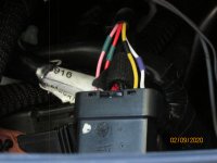
That would work fine. as long as the quality of fit on the male and female pins is accurate, then almost any connector is OK. I used ex-PC stuff as I had it knocking around. You can cut the 4 wires as they go into the black plug; this is what I did. I made short extensions to these wires to give more room for soldering and manipulation as the harness is short on slack. I think, judging by Burstner685's recent install, that it is the POSITION of the 4 wires in the black plug rather than their actual colours, that determines which of the 4 connects to which of the 4 from the stalk, as he had colours different to mine and it still worked. However, temporary connection there might be an idea to see if it all works as expected, then make permanent.The trick is remembering which colours you are using to connect things, take plenty of unambiguos fotos and make notes!
 
This post contains affiliate links which may earn a commission at no additional cost to you.
I have a cowl from an Alfa 147 which had cruise control, so I have the template for cutting the V shape. It's just knowing exactly where to cut on the Ducato cowl. Does anyone have any measurements for cutting please?

Sorry no. I made a rounded V, card template to fit the Alfa squib, then trimmed it, with lots of fitting checks, to fit against the upper steering column cover in the correct position.

Holding the lower cover to cut the slot was difficult. In an improving exercise I also trimmed a small piece off the squib. This second operation was facilitated by the connector used to extend the squib tails.

Another operation was to trim about 12mm off the lower edge of the rubber skirt on the lights/indicator stalk.
 
Thanks to all in this thread, just fitted cruise to my 2003 2.8JTD motorhome.

Fiat Stilo stalk from a scrap yard £5, and a brake light switch from GSF £11.74.

Fuse 27 was fitted but no 12v on brake light switch pin 3 so linked 3 to 4 and then onto stalk.
The other 4 wires were extended from the stalk and then soldered on to the pins that were cutoff the stalk wiring, these fitted nicely into the plug hidden around the back of the passenger side fuse box.

5 cycles of the IGN were enough for the ECU to recognise a stalk had been fitted and the dash telltale light up.

Road test completed and all good.

Cheers all.
 
Tom,

You do not have aircon, so of course you can. I used Delphi 1.5 male connectore from 3 way comp.Could not get them to fit into D018B, so individual heatshrink, then more heatshrink and small cable ties to make into pairs. Inserted into female half of connector, and each pair secured to connector body with further cable tie. Does not short, makes contact, and cannot come out.
My options are still open.

Since making the post above, I had a closer look at the Delphi 1,5 male pins and relevant downloaded Delphi drawings. There was a small section turned up through 90 degrees on the rear of the pins, which was not on the drawing. After some adjustment with small wiring pliers to bend the protruding part back down, I was able to exercise my option and obtained the result shown in the photo.
 

Attachments

  • Cruise Control Connector.JPG
    Cruise Control Connector.JPG
    2.7 MB · Views: 73
Thanks to all in this thread, just fitted cruise to my 2003 2.8JTD motorhome.

Fiat Stilo stalk from a scrap yard £5, and a brake light switch from GSF £11.74.

Fuse 27 was fitted but no 12v on brake light switch pin 3 so linked 3 to 4 and then onto stalk.
The other 4 wires were extended from the stalk and then soldered on to the pins that were cutoff the stalk wiring, these fitted nicely into the plug hidden around the back of the passenger side fuse box.

5 cycles of the IGN were enough for the ECU to recognise a stalk had been fitted and the dash telltale light up.

Road test completed and all good.

Cheers all.

I'm planning on doing this at some point, where did you find the wiring diagram for fitting it?
 
I believe that the modification originated in Italy, where it was extensively discussed on the camperonline forum.

There are at least two other threads on this forum with the same OP, which relate to the modification.

For your convenience I am attaching a link to the longer of the two, which contains useful links, and an attachment of my modified copy of eLearn drawing E5060, which I made for my own records.

https://www.fiatforum.com/ducato/475643-duato-x244-cruise-control-retrofit-victory-2.html
 
Thanks to all in this thread, just fitted cruise to my 2003 2.8JTD motorhome.

Fiat Stilo stalk from a scrap yard £5, and a brake light switch from GSF £11.74.

Fuse 27 was fitted but no 12v on brake light switch pin 3 so linked 3 to 4 and then onto stalk.
The other 4 wires were extended from the stalk and then soldered on to the pins that were cutoff the stalk wiring, these fitted nicely into the plug hidden around the back of the passenger side fuse box.

5 cycles of the IGN were enough for the ECU to recognise a stalk had been fitted and the dash telltale light up.

Road test completed and all good.

Cheers all.
For information. To obtain a supply at the brake light switch from fuse F27, you need to add a link between connector D160A pins 1 and 6. The connection at pin 1 should also be continued to the yellow lead of the Alpha stalk.
 
Hi all,

I am hoping you can help me with my cruise installation. I have fitted the 4pole break light switch and joined pins 3&4 to the yellow of the Alfa stalk and I have 12v there.

I have found the D018 plug and I have the relevant wiring in the cab from the ECU, black/yellow etc. I have matched the PIN numbers & colours from the plug to the stalk wiring and then soldered with heat shrink.

I checked the female plug to the ECU has wiring populated in the relevant PIN numbers but I still have no cruise working and nothing on the dash.

Has anyone any ideas of what to check next? I’ve even tried another stalk to confirm that the stalk wasn’t at fault.

Any help would be greatly appreciated

Thanks

ARG
 
The ECU needs several ignition cycles in order to learn that cruise control is connected. (@bofus reported 5 cycles at post #85 , earlier in this thread.)

12V is routed through the brake light switch via connectors D001B pin 2, and D004A pin A08, (Colour change here from grey/black to grey/green.) to arrive at pin A54 of the ECU.

From the brake light switch, the wiring is all pre-existing, but unproven.
 
Last edited:
Hi Communicator,

I have tried many ignition cycles and still nothing.

I joined the pins on the brake light switch and added the yellow cable to there.

Are you suggesting that I have to add some more wires from the ECU?

I have been at this for a few days now so I might be missing something trivial. I don’t have to enable anything with diagnostic equipment do I?

I have tried to go back to basics and rewire it again but it’s still the same, unfortunately.

Any help would be greatly appreciated

Thanks,

Paul.
 
"
======================================================

I joined the pins on the brake light switch and added the yellow cable to there.

Are you matching cable colours, or just using the pin numbers moulded onto the connector? On my vehicle the moulded designations did not match those used in Fiat eLearn.


Are you suggesting that I have to add some more wires from the ECU?

No but you may need to trace the detailed connection. (Some of the Italians had to wire all the way back to the ECU.)
=======================================================

I don’t have to enable anything with diagnostic equipment do I?


No but Ocwobio, the OP, did use Multiecuscan to check the operation of the switch and the wiring.


I have tried to go back to basics and rewire it again but it’s still the same, unfortunately.

With ignition on, are you seeing 12V +ve on the Grey/Black wire at the brake light switch? This is how the ECU learns that cruise control is installed.

I think that I have previously attached my amended copy of the eLearn wiring diagram E5060, but will repeat for your conveniance. I made the link between pins 1 & 6 of D160A, instead of at the brake light switch. I also connected the Alfa stalk via a 6 way connector. Otherwise the same as yours.
 

Attachments

  • Cruise Control 5060 Mod.pdf
    431.5 KB · Views: 53
Last edited:
Hi Communicator,

I have checked the wiring again and the vehicle is wired as follows:-

4-pole Brake switch - Blue (pin3) and Blue/Green (Pin4) are soldered together along with the yellow from the Alfa 147 stalk. I have 12v on the yellow when the ignition is on. I checked the Grey/Black Wire for 12v and I have 12v there.

I assumed that since I had found the D018 connector, the vehicle would have the wiring to the correct pins on the ECU? I removed the plug from the ECU and from what I can see, all relevant pins look to be populated (53-54-55-56-57-61-23).

I haven't opened the wiring harness sheathing to confirm the wires are there as I wasn't wanting to damage the sheathing until 100% sure that I had to go down that route.

D018 Connections I have made are as follows:-

Black plug Pink/Green (pin1) to Green on the Alfa stalk.
Black plug Red/Green (pin2) to Red on the Alfa stalk.
Black plug Black/Yellow (pin5) to Blue on the Alfa stalk.
Black plug White/Purple (pin6) to Orange on the Alfa stalk.

I think I have made all the right connections but I may have missed something.

I don't have MES to test the stalk operation, unfortunately.

Thanks for the E-learn, all of your help is greatly appreciated.

Thanks,
ARG.
 
Last edited:
***Update***

I have now got the cruise control working with the dash light illuminating too.

Believe it or not, the pin for the White/Violet in the multi plug under the fuse box had been bent when someone previously must have had the plugs disconnected.

I straightened the pin carefully and put the plug back together. Connected the battery and the dash/cruise light illuminated right away.

This may help other people in future who have issues like I had.

Many thanks for the help given, Communicator.

Thanks,
ARG
 
I am very pleased by your success.

For the benefit of others, the white/violet wire carries the cruise "ON" signal to the ECU.

Again for general interest, I am attaching a translation of a much earlier post on the Italian camperonline forum, and for any unfortunate soul trying to carry out this modification on a vehicle which is not pre-wired, a pinout diagram for the Bosch ECU.
 

Attachments

  • Cruise Control - Coppog.odt.pdf
    66.8 KB · Views: 68
  • Ducato 2.8JTD ECU Pinout.pdf
    116.3 KB · Views: 72
Just picked up on this latest bit of the thread- I'm away in mine right now and the mod has paid for itself many times already in reduced foot ache!Glad you got a result, another satisfied customer! No go out and enjoy it!
 
Finally, after only 2 years, I got around to cutting the lower column shroud to accept the new stalk control. I cut it a bit too long, but shape is OK. Can't get the lower 2 screws in, so will have a look in daylight tomorrow. It certainly aids support for the stalk that is held only by one screw! Bit of a faff, and slight misalignment, but it's still neat and looks 'factory'. Well, almost!
 
Back
Top