Technical X244 cruise control retrofit 2.8JTD 2005-factory parts?

Currently reading:
Technical X244 cruise control retrofit 2.8JTD 2005-factory parts?

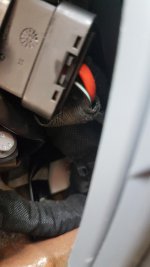
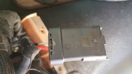
Can anyone tell me if this is the right plug ? Colours are slightly differentView attachment 206537

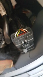
I thought not, initially. But it could possibly be the one, it is missing the aircon wires (yours does not have aircon then?) which may not be fitted to all, as Communicators van does not have aircon, yet has the wires- maybe not all do?. The colours of the 4 wires look like, IIRC, mine. You could find out for sure, by tracing them to the main engine ECU. It is a 2 person job, ideally, one to hold a multimeter probe on the relevant ECU plug pin in the engine bay, and one to place the other probe on the terminal in this plug, after you have disconnected the two halves. You could do it single handed, making something so one probe fits into the black plug socket pin hole and will stay put, then go outside and place the other one on the ECU cplug pins in turn, noting continuity or not. You will need long probe leads!The ECU plug pins you need to check for continuity from your black plug inside being 53, 54, 55, 56, and 57. I don't recall which colour is which pin, but for now all you need to do is find if these wires are the right ones. This will give you a 100% sure way of knowing you have the wires in the dash for a relatively easy install- certainl loads cheaper than an aftermarket unit!
 
Last edited:
After a studying of the photos provided by Mandasvan, I agree with Ocwobio that the connector shown may be D018B, which carries the cruise control connections.

D018B as I have previosly stated, is a 6 way hybrid connector of Delphi manufacture, with the centre two pins (3 & 4) being larger than the others (hybrid). Applicable colours are pin 1 pink/green, pin 2 red/green, pin 5 yellow/black, pin 6 white/violet.

A possible cause of confusion over the wire colours could be that on some vehicles, the wire colours are overlayed (printed?) over a white body, some of which remains visible.

The connection from connector D018B, to the ECU are routed via connector D004A, which is located under the engine bay fuse/relay board. The relevant pins are B01 to B04. If these pins are populated, the pre-installed cruise control wires are in place. (eLearn suggests a wire colour change from white/violet to black/violet at pin B04.)
 
Thank you to all the contributors to this forum for the valuable information regarding the cruise control mod. I fitted it over the weekend and test drove it today. Works perfectly!
 
I've read through all the posts with great interest and this is a job I want to do on our motorhome.
I've stripped dash out and the D018 connector only has 4 wires in one side and 2 in the other. Can i still retrofit cruise control and if so can someone point me in the right direction please.
Been trying to get brake light switch out. What a bas**rd. Still struggling.
 

Attachments

  • dash 1.jpg
    dash 1.jpg
    48.9 KB · Views: 36
  • dash 2.jpg
    dash 2.jpg
    64.9 KB · Views: 45
  • dash 3.jpg
    dash 3.jpg
    55.4 KB · Views: 43
Hi,

From your pictures I deduce that you do not have air conditioning installed. On connector D018B the thick red wire and its partner in the centre two large pins are the supply for fan speed 4 with aircon, and the clutch control for the aircon compressor. In your pictures they are not continued on the engine bay side of the connector. Hence my deduction of no aircon.

The four smaller wires in the outer four pins of the other half of the connector are those associated with cruise control. The colours should be pin 1 pink/green, pin 2 red/green, pin 5 yellow/black, and pin 6 white/violet.

I suggest that after studying what is required, you first move should be to aquire the Alfa 147 cruise control stalk. A complete column switch assembly was recently advertised on Ebay for £20 +£5 postage, (linked in previous post).


As regards the brake light switch I think that several/all of us have struggled. See Ocwobio's thread Ocwobio used brute force, while I did some filing of the metalwork behing the switch, so as to allow the connector to be removed. If your new switch has a longer length of the operating rod exposed, do not worry, it is adjustable with care. After measuring the old one, I squeezed mine in a vice, but a G clamp should suffice.
 
Last edited:
Tom, it looks like the one. Has your van got aircon? It seems the thick red wire that would normally exist both sides of the plug is missing from one side. Also, the colours on the 4 thin wires are different. I would advise checking them back to the engine bay fusebox or even the ECU. There is info about which ECU pins you need connexion on at the black plug on here somewhere, but IIRC 53 to 58, missing one out, but would need to check. What year is yours?
Yeh, the brake switch is one of those.....try turning it to disengage the bayonet, tilt it in towards the centre of the vehicle and pull it down slightly, forcing it somewhat, then disconnect the plug and wires. This will give a bit of room but you may be surprised how brutal you need to be. Once the knack is discovered, it won't be anything like as bad. Just listen for anything that is oviously cracking! An d back off, lol.Proceed at your own risk, but it can be done. On my new switch, the length of the plunger was too long-the domed end was cut off to make it equal to the old one exactly, the lack of the dome is of no consequence in its operation. I used a stout craft knife blade, the plastic was sufficiently brittle to make a clean break as the dome pinged off into the undergrowth.
 
Last edited:
Thanks for the prompt replies.
It's a 2004 2.8jtd without aircon.
I'll have another go at the brake light switch tomorrow. Bloody back's killing me. lol

Ben there, done that, had the shirt, now using it as a duster!
The worst aspect of doing this mod, I agree, is poor access for those less mobile, like me. I had visions of living near the pedals when I got down there to do mine.

This is THE place for info, as you will find out. Welcome!
 
Got the bloody thing out at last. Pushed and pulled and cursed and in the end I got a pair of grips and pulled down slightly against the springiness of the bracket and out it popped.
Need to source an Alfa stalk now.
 
Doh! That's why it's so cheap, which it isn't for what it is. I should have spotted it from the LCSW19-2 code. Keep looking.

May I re-emphasise that it is most important to take extreme care when cutting the notch in the lower steering column cover, if you want a good finished look.
 
I have a cowl from an Alfa 147 which had cruise control, so I have the template for cutting the V shape. It's just knowing exactly where to cut on the Ducato cowl. Does anyone have any measurements for cutting please?
 
Last edited:
All parts ordered then the fun can commence.
I've been looking at the D018 connector and wondering if I can split this and buy 4 male connectors to connect onto stalk wires and simply plug them in or does D018 need to be joined together. Hope this makes sense.
 

Attachments

  • 20200614_150820.jpg
    20200614_150820.jpg
    2.6 MB · Views: 38
  • 20200614_150835.jpg
    20200614_150835.jpg
    2.7 MB · Views: 34
Hello again!

"As you have aircon, if you wish to bypass the black Delphi connector why not leave it in place with the aicon connections, and divert only the four cruise control connections?"

That is what I intend to do. A single Molex will the suffice, 4 way and will take the current involved. I even though about picking the 4 wires up in the engine bay nearer to the fuse box therein, and going in thru the dash at the RHS, I will have a look to see the possibilities in the next day or two.
As for too much info- not a bit of it! If I can't accomplish this job now in light of the foregoing, well, I deserve to watch Barbie doll unboxing videos on youtube for the rest of my days.

I've ordered all the parts and got dash stripped right out. Am I right in thinking I can cut the 4 wires at the D018 connector and fit them into a new 4 way along with the 4 wires from the stalk.
Something like this.
https://www.ebay.co.uk/itm/Quality-...356727?hash=item1eb4718277:g:2ScAAOSwanRXhhZj
 
This post contains affiliate links which may earn a commission at no additional cost to you.
Hi Tom.
I can't see why the connector should not stay apart, as the 2 wires in the one side don't connect to anyhing on the other. Just confirm these 2 don't liven up with the ignition on just in case. The actual pins in the 147 stalk plug as it should come to you, if removed from the Alfa plug housing, will fit nicely in the side of the black plug with the 4 wires, but the problem is, they won't fit into the mating half of the plug as the recesses for the pins are too deep, and thus they won't lock in place. Although I suspect that, if I read it right, one user has managed to do this by pushing them into the black plug empty holes (you would need to have any wires soldered to them first, making sure they are correctly connected) then pulling them thru from the connecting side with needle nosed pliers, all the way in. Unfortunately, the correct ones are not AFAIK available to mere humans.

If you can find a way to make a support for them, and make sure they don't short, you could then perhaps secure this support to the black plug.( IIRC Communicator managed to rig something up likewise, unless I have misunderstood him). Then all you have to do is route an extension for these 4 wires to the steering column area for stalk connection, then the 5th stalk connection-the yellow one- is merely taken to make a 3 way connection to the bridge wire on brake switch pins 3 and 4. You should then be in business.

That said, if I was doing this again, I would make more effort to use the original black plug halves, the 147 stalk plug pins being a good mating fit in the 'short' side of the black plug, but the other side being too deep as mentioned, I have some hard drawn copper wire, about 22SWG IIRC, I could solder some onto the 147 stalk pins and as this copper wire is quite stiff, it may be possible to then push them deep enough into the black plug vacant spots, leaving enough of a tail to solder on to. once they were in, I suspect they're in for good if it works, but leaving a tail is then easy to solder to. Let us know how you do with it mate. It is well worth it and very satisfying. And relatively cheapo!
 
All parts ordered then the fun can commence.
I've been looking at the D018 connector and wondering if I can split this and buy 4 male connectors to connect onto stalk wires and simply plug them in or does D018 need to be joined together. Hope this makes sense.

Tom,

You do not have aircon, so of course you can. I used Delphi 1.5 male connectore from 3 way comp.Could not get them to fit into D018B, so individual heatshrink, then more heatshrink and small cable ties to make into pairs. Inserted into female half of connector, and each pair secured to connector body with further cable tie. Does not short, makes contact, and cannot come out.
My options are still open.
 
Back
Top