Technical lambda sensor wiring help

Currently reading:
Technical lambda sensor wiring help

Joined
Nov 26, 2004
Messages
15,373
Points
3,148
Location
southend on sea, essex
first things first in my turbo revival!

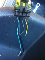
ok first of all, all wires have been cut, no plugs.

my lambda sensor has 4 wires, 3 wires are wired into the loom, 1 is not.

can someone tell me will it be the same as a standard 1.1 cinq? (so i can go to a scrappie and take out part of this loom)
 
i got a bit from a seicento but its not right, so i hope someone with a cinquecento can help,

the 4 wires are:

green
black
blue/yellow
brown/green

i just need to know the order of them (on the car side of the lambda sensor wiring) they are numbered as in the picture below (obviously ignore colour wiring as its seicento)
 

Attachments

  • IMG_1423.JPG
    IMG_1423.JPG
    1.8 MB · Views: 72
Well it cleary needs all four...

blue and yellow cable from ecu terminal 29
blue and red cable from ecu terminal 12
grey and black cable from main relay terminal 6
black and blue cable to ground (31)

6 and (31) will go to the two white cables on the lambda as these are for the heater. The element is non polar so it shouldn't matter which way round.

That leaves 12 and 29 which it is very important to get the correct way round. Since 3 of the cables are already connected in the loom this should be fairly simple to work out?

You could measure the output of the two remaining lambda cables with a multimeter while the engine is running, you should get an output anywhere between 0 and 1v. This should be enough to enable you to work out the polarity .

The positive lambda cable needs to go to terminal 29 and the neagtive terminal 12. The lambda generates its own voltage (around 1v), this is how it works.
 
Last edited:
Actually after a bit of thought it's quite likely 12 is the ground for the heater (one of the white cables) and the Earth (31) is, well the earth (for the signal). The reason for this being the ECU probably switches the heater off once the lambda is up to temperature. I'm not sure if the ECU is this clever but it seems very likely. The manual is vague only describing 12 as negative lambda input and 29 as positive lambda sensor input.

Maybe woj will know if the ECU turns the lambda heater on and off. If it does 12 has to be for the heater as otherwise the ECU would not be able to control it.

Still if some one has one of these prewired to hand it would be a lot easier. LOL
 
Well there both still grounds so it would do no harm just not work right, but yes it would be a lot easier to copy one that's prewired. :)

As for the technical mumbo expect more I'm afraid, this is the Cento technical section where most of the techy people hang out. :D
 
12 is the lambda signal ground, 29 lambda signal positive. The heater
is connected, one goes to +12V fed from the fuel pump relay (global power supply for fuel related components), the other one goes to ECU pin 17.
The only thing I do not remember is which cable on the lambda plug is
which, two on one side are the heater (here I don't think it matters which way connected), two on the other side are the lambda signal. I would have to go to the car to check, can't be bothered at the moment.
Honeymonster: where on earth did you dig out the pin (31) thing. You surely do not mean ECU pin 31 :confused:
 
@Honeymonster: where on earth did you dig out the pin (31) thing. You surely do not mean ECU pin 31 :confused:

So I was right with my original assumption 17 and (31) are the same cable. Didn't notice it was also connected to the ecu now it makes more sense. (y)

I put it in brackets as it was alone on the diagram not stipulating what it was.

My pin out was from the Sei ecu block so didn't include the other 2
conections.

cinquecento_SPORTING_wiring_diagram.jpg

Edit: It also shows it's just a ground (see fuel pump etc.) so if it really is the heater ground the ecu would have no control over the lambda heater and it would stay on permanently.
 
Last edited:
The 17th pin on the ECU has always been a little bit of a mystery to me. I also noticed long time ago that it is bridged directly to ground. The first thought was that perhaps the ECU checks the heater work on pin 17. But disconnecting the heater does not cause any ECU disturbance.

I am really poor with electrics and stuff - isn't it possible that the ECU somehow sinks in the +12V through this PIN to turn off the heater?
 
I am really poor with electrics and stuff

No you're not... :)

isn't it possible that the ECU somehow sinks in the +12V through this PIN to turn off the heater?

No it would have to be in on the feed side to work as a divider (or wired in series), they simply wouldn't bother when they could use the ecu to switch it off (a simpler more sensible approach). (31) is a general ground with lots of things connected to it, 17 is just an ECU ground nothing more according to this diagram. This is why I suspected 12 as it could work by removing the ground (like most things switched by the ecu) turning the lambda heater on and off as required. Also the my pin out has a vague description I guess we will know for sure when someone actually coughs up a picture of the cables. LOL

I love discussions like this, not just finding an answer but truly trying to understand how things work. :D
 
Last edited:
Just looked at another Fiat ecu wiring diagram (the 8f) clearly showing because of its dual Lambda sensor conectors, the Lambda heater is permanently on. Interesting beacause on most modern cars the ecu controls/is in circuit with the lambda sensor for at least two reasons. The first being the ability to turn it off/maintain its temperature to save unescessary ware. The second giving the ability for the ecu to give a fault code for a failed heating element.

Anway we still need a picture of a terminated connector from a Cinq to help Beau, I have the Lambda half in my boot but we still need the car bit.

However if no one comes up with the goods I think it's fairly safe to say:

blue and yellow cable to - Black (Lambda) Pin 1 on my Lambda
blue and red cable to - Grey (Lambda) Pin 2 on my Lambda
grey and black cable to - White (Lambda) Pin 3 on my Lambda
black and blue cable to - White (Lambda) Pin 4 on my Lambda
 
Back
Top