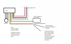
Does anyone have a cop of the cinq codebox diagram by any chance?
I need a pin out and where the wires route too. At the moment this one seems to tap into hazards, and indicator fuse.... Is that correct?
Thanks
X
I need a pin out and where the wires route too. At the moment this one seems to tap into hazards, and indicator fuse.... Is that correct?
Thanks
X