Technical IAW ECU Live Mapping & Tech Info

Currently reading:
Technical IAW ECU Live Mapping & Tech Info

thanks for that latest update... its the bit ive been waiting for.

(y)

do you know anymore about rpms and manifold pressures at which 14.7afr is kept?
does the engine run at 14.7 while cruising?
I run mine at near 16.0 afr at low throttle/cruising to try get good economy and it works well. just wondered if the stock ecu does this to and to what extent?

Well, there are these 4 correction-speed tables I talked about. It is difficult to see what they do in practice, my AFR module shows 14.7 almost all the time at part throttle. 16-17 AFR I only get at soft deceleration (closed throttle, low MAP, low rpm, but above idle), but then this is outside of lambda operation range. The one occasion I get 15-15.5 AFR for a quick moment during sudden acceleration, despite lambda operating and acceleration enrichements. Otherwise it basically reads 14.7 at part throttle with bigger or smaller variations depending on the load, but it always oscillates around 14.7.

These 4 tables basically say how aggressively the correction should be changed under different load conditions. For example we are at 60kPa and 3000RPM, the tables says:

  • one table says: "when still rich change correction by A"
  • second one "when still lean change correction by B"
  • third "if overshot (lean changed to rich or vice-versa), reduce correction by C"
  • fourth "if overshot from lean to rich, keep the correction for time D" (and only after time D keep applying tables 1-3.)

So it stays at 14.7 most of the time, and the core reason for this is I guess emissions, at 14.7 the catalyst operates at its best.
 
Last edited:
Ahhhh I get it... them 4 tables act as a sort of PID controller...i guess ([ame="http://en.wikipedia.org/wiki/PID_controller"]PID controller - Wikipedia, the free encyclopedia@@AMEPARAM@@/wiki/File:pid-feedback-nct-int-correct.png" class="image"><img alt="" src="http://upload.wikimedia.org/wikipedia/commons/thumb/4/40/Pid-feedback-nct-int-correct.png/300px-Pid-feedback-nct-int-correct.png"@@AMEPARAM@@commons/thumb/4/40/Pid-feedback-nct-int-correct.png/300px-Pid-feedback-nct-int-correct.png[/ame]) this is what MS uses for most operations that have targets (aft/idle control/boost control)

im guessing the ecu stays at 14.7 for emissions. I guess running at 16 would leave noting for the cat to work with...
 
Wow, now I learned something valuable (y) As you say, now that I think of it, indeed it is exactly something like this. The only problem with the ECU is a relatively limited computing power, hence a "simplified" operation (couple of tables) of the PID algorithm. I should really read this article, maybe some things will clear for me.

Regarding the idle valve control, so far I failed to dissect this part, it is probably simple, but the code that does this is just horrible (n) And IVC also uses autocalibration, which makes things even worse.
 
glad I have helped. :)

the idle control i dont think is worth digging into much... not worth the effort.
it should never need changing (unless you need an above standard idle)

Don't underestimate. The target idle RPM is actually simple, there is a table for that, a function of coolant temperature. So changing my idle to 1000RPM was a piece of cake.

However, idle control in general should not be dismissed so easily. If you look at it as a stabilizing system you have to realise what consequence, for example, for it lowering (or raising :D) engine compression has. Lowering compression means less power, less power means more air to keep the same RPM under the same conditions as before. What follows is, if the initial idle valve position does not hit the sweet spot, the algorithm will have more difficult time finding the right spot and thus more rough idle. What I am quite sure about is that there is a high resolution load dependent table that gives the initial idle valve opening for every load (in fact, for higher loads it says hex FF meaning full valve opening), which is then corrected based on the RPM readout and current target RPM. If this table is off, more corrections are needed. It is exactly parallel situation to fueling. Changing the compression ratio is equivalent to putting bigger injectors in, and should also be accounted for in the IV table. Luckily, the 18F program has IV autocalibration, which can compensate for this situation and it seems it works great in practice. That is, in the long run it can remember that all IV values in the table are off because of some reason, for example changed engine compression ratio, or leaking IV. But... I do not know the details of the calculations to establish the IV position equally well as I know it for the fuel. For the completeness: 8F program does not autocalibrate IV, 16F most likely does not either, 18FD most likely does too.

So this should have been titled ;)

Idle Control
 
I understand how complex the idle control is.tuning it I'd very time consuming. AS you said...idle speed is effected a lot by changes.

In the end I blocked off the valve and set the idle manually. Never had idle control on carbs.
my car starts first turn of the key even at -8.
Idle is controlled a bit by ignition timing (same as standard ecu)

Good thing with no idle control is if anything goes wrong (split hose) you will not have the idle valve hiding it
 
Fuel Autocalibration

Autocalibration in itself is quite simple, but this simplicity has actually certain complexities in fueling when the fuel tables are not right on spot. AC is something that compensates for general wear of engine components and for the fact the fuel tables are by default on the rich side.

To start with, autocalibration (AC) parameters are applied to fuel always, as long as this feature is switched on in the ECU. On is the default, AC can be switched off (and back on) through the diagnastics interface. Each time it is switched all AC parameters are reset to zero. AC will be applied even during open loop, low coolant temperatures, etc. Also when the O2 sensor is dead. What follows is, a very unlikely scenario like this is possible: your O2 sensor starts to break down, showing to the ECU rich state, so the ECU leans out the fuel and keeps recording it in AC parameters. Then the O2 sensor finally dies, but the AC parameters stay set, and your fuel is kept lean. There are also related consequences when some fuel table cells are off, this I will describe at the end.

On the other hand, AC parameters are calculated and updated only when the engine is in closed loop mode, and additionally some other conditions are met. RPM has to be between 1000 and 4500 (apart from idle, where the bottom 1000 RPM is not considered), MAP has to be above 32kPa and below whatever is currently switching off closed loop (see previous part), and the engine has to be fully warmed up, coolant temperature above 77 degrees C IIRC.

The rest is quite simple. If the lambda correction stays above or below 1.0 long enough a corresponding AC parameter is updated (a constant step value is added or subtracted). By corresponding I mean the parameter that currently applies to the engine condition is changed. There are four:

  • Idle
  • Light load (MAP < 60kPa) with the charcoal canister diactivated
  • Light load with the charcoal canister activated
  • High load (MAP > 60kPa)

These I named AC1, AC2, AC3, and AC4 correspondingly in the section on fuelling. AC4 is applied always (it is part of what I called global fuel corrector), and AC1, AC2, AC3 are applied exclusively, depending on the state of the engine again.

Note here the difference between the engine state when AC parameters are updated and applied. The two are not equivalent. For example, let's say we are first at light load (other conditions for AC update are met) and AC2 is updated (others are untouched), then we go to high load and AC4 is updated (again others are untouched). At the same time and all the time, the current values of AC1-4 are applied to fuel calculations. When idle (and regardless of any other engine conditions) AC1+A4 are applied in proper places, when at light load (again, regardless of other conditions) with canister on AC3+AC4 are applied, and when at high load with canister on also AC3+AC4 are applied. Hope this is clear enough.

A side note on canister activation, never cared do analyse this in full either, but it seems it is usually switched during light acceleration. Then the fuel vapours help to enrich the fuel mixture during acceleration.

OK, so we have 4 AC parameters for the whole range of engine operation. This is not much and when you think about it, it is actually quite weak. Especially when your fuel map is not entirely spot on it has the following consequence. And this one is actually very likely, I have witnessed this happening during my experiments. Suppose you have one rich spot in the fuel table, which happens to be your usual crusing spot. Beacuse of this rich spot, the AC parameters will be very quickly brought down to a seriously negative value. Then all of a sudden you enter WOT, lambda goes into open loop, but the ECU remembers the negative AC parameter and keeps applying it and you get a lean mixture during WOT while you wanted rich. This is the single reason why switching over ECUs between engines they were not tuned for is not a good idea. The fact that they work does not mean that they are not doing harm to your engine. This is especially important for turbo applications. By no means you want AC to bring your fuel down in boost because of rich underboost spot in the fuel table. For this reason my turbo version of the 18F program resets all AC parameters everytime boost is detected.

You would think that AC parameters is something that stabilises over time. This is only true for the idle AC parameter, all the others jump up and down like crazy within seconds intervals of engine operation. Finally, all AC parameters can be observed through ECU diagnostics. In the 8F/18F the following ECU request codes can be used:

  • hex 24, 25 give AC1
  • hex 22, 23 give AC2
  • hex 26, 27 give AC3
  • hex 28, 29 give AC4

AC works the described way in 16F and 8F/18F ECUs. For 18FD it is different. To the best of my current understanding there are only two types of AC parameters: light load (AC2 and AC3 combined) and high load (AC4). But they are not single parameters, but there are 6 of each and they are RPM dependant. Meaning that AC parameters are separated into RPM ranges. Other details of AC operation in 18FD ECU are not yet clear to me.
 
Turboing it!

Most of the work on the ECUs I have done with the aim of making them work with a turbo. And smooth too. Hence the need to understand everything that happens there, so no unpleasant surprises would surface out. Also because of this I concentrated on the 8F/18F ECU, this is the one for my turboed engine.

Actually, the most and almost only issue is for the ECU to correctly interpret a wide MAP sensor. I used a 2.5bar one of a Fiat Coupe. Approach A. is to simply connect the MAP to the ECU and pray for the best. This operation will change the scales of MAP dependent maps. For example, 20kPa will roughly stay 20kPa (0.25V on the sensor), while the atmospheric pressure will not show 4.75V any more, but rather something around 2V, while 4.75V will indicate 1.5bar of boost. But scales are not the only thing, all the other MAP dependent calculations will deviate too. Recall, for example, that the fuel base uses a direct readout from the MAP sensor. In effect, your fuel dosages will be at least twice as small as before. Moreover, the ECU will no longer know what an atmospheric pressure is, because it is not at 4.75V any more. A bit messy. If you want to turbo the ECU this way, it will work, but you will need to fully redo the main MAP dependant tables (fuel, ignition) and hope that the rest will work somehow. You will also loose the resolution of the main maps. Now 2.5bar range needs to fit into 16 cells, instead of just 1bar. In practice this approach works (lots of folks in PL do it this way), but the reports are that the ECU gets flooded with errors, the initial idle is very rough, lambda correction kicks in when not desired etc.

Looks hopeless, doesn't it? Defo not the quality I would expect from a decent turbo ECU. So I planned for simply analysing every single bit of code that uses MAP values in the calculations and rescale the internal values accordingly for the 2.5bar MAP sensor. This also looked hopeless after a while, there is way over 50 places where MAP is used in scales and calculations. Some of the calculations were far from clear too.

But the story has a happy ending, and this thanks to the ECU program itself, and the way it keeps MAP sensor readings. The 8F/18F program is special in this respect, almost as if it were written for a turbo engine ;) Neither 16F nor 18FD can be subjected to similar trick. The 8F/18F program keeps the current MAP value in two different cells. One is 1-byte cell, with the 0-255 range and the data conversion exactly as in the diagnostics document: DATA * 3 gives MAP pressure in mmHg. The other cell is 16 bits, range 0-65535, and keeps the same value directly in hPa. For example, the hex value of 00FF indicates MAP pressure of 255hPa, while 0400 indicates MAP pressure of 4*255=1020 hPa (practically atmospheric). Most of the range of this 16 bit cell is unused, what a waste! It could in theory store MAP pressures of up to 65bar. Moreover this cell is used for the most important big maps (fuel and ignition).

So, my plan was this. Change the MAP sensor reading procedure (voltage data to actual data converter) so that the 2.5bar sensor is unrecognisable to the ECU when the pressures stay below boost. When, say, the voltage is 2V (roughly) which for the 2.5bar sensor is around atmospheric, the ECU will see FF in the first cell, and 0400 in the other cell. This means you can put 2.5bar sensor into your N/A and still run the engine smoothly. The other part of the conversion procedure is changed such that the second cell correctly records boost pressures, while the small cell treats all boost pressures as atmospheric. So at 4.75V it should store hex 09C4 = 2500 decimal = 1.5bar of boost. The first "small" cell gets locked at FF showing at most atmospheric pressure.

And this is actually enough. So it happens that the small cell is used in all kinds of tables and calculations where boost is (or can be treated as) irrelevant. The big cell is used for the main maps, including the fuel and ignition and this is where we need to know about boost to have additional fuelling and proper ignition. What remains is the size of the MAP scale. It is still 16 cells, killing the resolution of the maps, even though the maps interpret the boost values correctly. After a quick thought I simply resized these scales and related maps to 32 cells for MAP. This allowed me to keep the original 16 cells for under boost values and gave me fresh 16 cells for boost.

This is almost it, but not quite. The ECU program is designed in such a way that MAP pressures close to atmospheric make it go into WOT state, effectively flattening the ignition MAP. Pressing the accelerator to the floor will also cause WOT state, which is now senseless, because despite WOT we can still have a whole range of pressures in the manifold and not just "close to atmospheric" as the ECU assumes. All in all what needed to be done was to neutralise the WOT state all together, simply by wiping out the code that switches a corresponding bit on. Then I also made the MAP pressures that make the ECU go into open loop mode a bit lower, so that I can get proper (below 14.7AFR) fuelling well before the boost kicks in. This was especially needed at lower revs, where close loop is effective until the very end (atmospheric pressure). Talking about auto calibration, I also reset all AC parameters every time the program discovers boost. This is to stay clear of any mess AC can cause in the fuel, see previous part. Also at boost the program gives additional fuel by default, so that the corrections in the main fuel map need not to be drastic (to get 11.5 AFR the main fuel map may run out of value range, hence we need to have extra fuel from the start, then correct it to 11.5). A cherry on top is a poor man's boost control, or rather I should call it boost defender. That is, an additional, ignition cut that also depends on high enough MAP pressure. To prevent unpleasant surprises when the wastegate gets stuck closed or somebody plays with MBC (that I do not have yet :D).

There are of course some fine details that I do not write about. The second part of turboing it is to put bigger injectors so that injection times stay within the limit of one engine rotation (see previous parts) even on high boost. This part is easy, I simply rescaled some fuel maps accordingly to the change of the injector size and that did the trick.

Then there was a dyno time to get the tables right on spot, the result can be found in my turbo thread (see my signature). I am also planning to record a short movie showing how this works in practice, but I need to wait for a slightly better weather ;)
 
Hi,

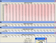
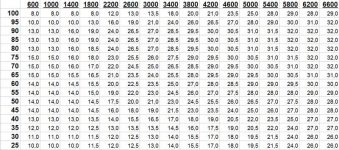
can you post the original part-throttle tgnition map? I managed to find the table inside the bin, but i'm not sure what revs and kpa each row and column represents.

I'm tuning my 1.2T Sei with Megasquirt and original ignition map would be of great help.

Thanks,
 
Hi,

can you post the original part-throttle tgnition map? I managed to find the table inside the bin, but i'm not sure what revs and kpa each row and column represents.

At what address and which bin? Only curious how successful you were...

For the map, see the attachment, 18F ECU, full thing, NY gift ;)

EDIT: horizontal labels for PT are hPa.
 

Attachments

  • ignition12mpi.png
    ignition12mpi.png
    50.2 KB · Views: 1,441
Last edited:
Yeap, that's the map i found, only wrong axis interpreted.
 

Attachments

  • Punto75ignitionmap.jpg
    Punto75ignitionmap.jpg
    73 KB · Views: 639
Yeap, that's the map i found, only wrong axis interpreted.

That is the tricky bit in 8F/18F program, the main MAP scale used in the quoted table is reversed (as opposed to most of all other scales which are sorted small-to-big values). Another curious thing in the IAW programs is the changing density of the MAP scales, they are by far not evenly spaced. Anybody can guess why? (I have no clue (n)) RPM scales seem to retain certain regularity, low RPM bigger density, higher RPM smaller density.
 
My wife's Panda 1.2 60ps, checked through OBD scanner, varies its idle timing from 9 to 15 degrees. Engine acceleraters at 15 degrees and decelerates at 9. That is the way the Panda keeps its 850 rpm idling. My Sei does quite the same (checked by ignition stobe through the gearbox window).

Haven't quite figured out how this will be translated to the load/rpm map of my MS-II...
 
cool...

are you trying get up the idle advance timing? if so its only 4 timings and the loads.

load increases at idle drops. its better then having it rpm dependent... turning lights on causes higher engine load... this will increase timing to keep rpm the same.... where if it was rpm dependent, turning on the lights will drop the rpm then increase the rpm causing bad oscillations
 
Craig, yet again you touched an interesting subject. In the maps I have quoted, the "Ignition Closed Throttle" is responsible for all "fuelled" closed throttle conditions, which includes idle. With the addition, that during idle this ignition is constantly corrected according to RPM fluctuations above/below target RPM, see the part on Ingnition above. It is not MAP pressure dependent from what I can tell. In parallel IV tries to provide enough air to get the right RPM. So yes, I would say this system is a bit weak. But then, on the other hand, as long as you only turn on the regular electric receivers, the load does not change that much (5-10kPa tops me thinks). This is small enough to have "RPM only" ignition timing.

Now, the interesting bit is something I witnessed a few weeks back. I hooked up a 12VDC portable hair dryer to the lighter socket and turned it on (my mistress uses it to defrost her car) to see what will happen. I expected drastic load increase in terms of MAP pressure change. Instead, the ECU chose to increase the idle RPM drastically (I think to around 2500). I am not sure why/how this happens in the program, but perhaps the IV could not provide enough air to keep the target RPM and hence it increased the target idle. And perhaps technically the ECU was not in the "idle" state anymore...
 
Hi,
I am also playin with IAW 8F.5T ecu and it would much nicer to have bin definiton file instead of hex. Did you happen to find any xdf file for our ecu?
 
Hi,
I am also playin with IAW 8F.5T ecu and it would much nicer to have bin definiton file instead of hex. Did you happen to find any xdf file for our ecu?

Nope, I made one myself :D If you have figured out the map addresses making up the xdf file is a piece of cake (y)
 
Back
Top