Technical Cambelt Change

Currently reading:
Technical Cambelt Change

i Frank !
i went to check my locking tools and the service manual , also whatched youtube video on it , i already changed the timing belt with them about 2 years ago , no problems at all !
And ... i'm 99% sure those ones in the picture are the intake cam ones !?
 
Phil sorry, I can't help myself, just to be sure: here you see a picture from both the M1 (grey) and M2 (gold) exhaust cam shaft locking tool.
Easier to identify: the M1 locking tool (183 engine) has the top at half past 12 and the M2 locking tool (188 engine) has the the top at exactly 12 o'clock.

Regards,

Frank

For out MkII, 2005, Engine 188A6.000. I bought the offical Fiat cam lobe timing blocks P/N: 1870697000/1 @ 2 degrees and 1870697000/2 @ 3 degrees
 
The intake cam shaft locking tool (what a word): with "A" (for Aspirazione = intake) engraved.
The outlet cam shaft locking tool: with "S" (for Scarico = exhaust) engraved.
 
Hi, I have finally bitten the bullet and started the cambelt, waterpump change, encouraged by all the success seen on the forum. I have an Le 98 model with working aircon and the Gates kit for belt 168 teeth, tensioner and water pump, Universal yellow coloured glycol coolant ready to use.
So far I have managed to remove the wheel liner complete, the coolant header tank and the dreaded belt cover, I released the auxilary belt but was unable to remove it completely because there is not enough room for the belt to slide past the aircon pully and the suspension bracket. I can only assume that I need to either support the engine and release the suspension arm or move the body of the car to increase the gap somehow. The auxilary belt can stay loose nd out of the way I think and I can work around it.
I spent an hour trying to release the wire connection to the aircon but failed. Stepping back I can’t see why I need to remove this wire, it does not seem to interfere with the belt change but I may have to return to it.
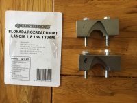
So far okay, then went to look at exposing the flywheel via its cover and checking theat my Sealey flywheel locking tool fits. Cover removed and the Sealey locking tool model VSE2394 does not fit. I looked to see if the flywheel teeth could be seen so that a pry bar could be used to block the flywheel. No luck there can’t even see the flywheel teeth through the opening. The plate I removed is in the position shown in the manual.

I have the 50mm M7 bolts for use with the cam locks.

Any suggestions on where I can get a suitable flywheel lock or a work around? I have seen sugested that if the gear is engaged this is sufficient.

Does the aircon lead really have to be disconnected?

I viewed the Youtube german video of the belt change and noticethat he did not use a flywheel lock when loosening the inlet flywheel, is this safe?

Before I go any further, any advice is welcome. Cheers SteveD
 
I can’t answer the question about the air con pump as mine doesn’t have air con, but, when I did mine, I didn’t use a flywheel lock

Got it all back together and it started first time and all runs perfectly
 
The "B" crank aux. belt pulley has four bolts bolts retaining it. I assume you want to lock the flywheel so you can undo them not having an air gun/similar?

You will need the help of another person but what you can to is the use a rod/screw driver to lock the flywheel BUT NOT on the teeth you can't see but in one of the gaps in the pressure plate cover to flywheel interface. NOTE. This will be on or off TDC alignment but as you are only loosening the crank pulley bolts you can then rotate the engine again in the correct direction to get TDC back again.
 
Last edited:
You should not need to lock the flywheel. You might have to lock it to get the 4 crankshat pulley bolts loosened but after that you just need to ensure that the engine is a TDC and then fit the cam lobe blocks. To get TDC then use the inspection windows on top of the gearbox bell housing. You will see 3 markers/pips/notches on the bell housing and a notch in the flywheel. Align the flywheel notch with the rightmost bell housing marker and then put the car in 1st or reverse gear. TDC is very unlikely to move when fitting the belt due to the very small radius and leverage that the belt drive has on the crank.
 
Hi s130, thanks for your help. I have the cam locking tools in place but need to remove the crankshaft pulley bolts the 4 rib bolts. They should be 25Nm. I cannot source the flywheel locking tool number 1860 84600 but I haven’t tried FIAT.
Without a flywheel lock and with the gear engaged in reverse or 1st is this safe enough to undo the bolts?
Or If I can borrow an impact bolt gun would this do the job of undoing the bolts without putting strain on the camlocks?
Grateful for the input.
 
When using a ratchet 1/2 inch drive wrench then the force you apply is progressive and most likely to turn the engine.

Have you tried using a not ratchet drive and then tapping it with a hammer to provide that rapid inertial pulse? If that does not work the you will have to lock the flywheel with a screw driver as I suggested but that ideally requires a second pair of hands.
 
Thanks, I will try that shock treatment. Unfortunately it will have to wait till next week now but will let you know if that worked.
Cheers
SteveD
 
Hi, I thought it was about time I updated my progress. I thoought I would try and source a flywheel lock tool number 186084600. I asked Fiat Uk who said the tool was no longer available but its replacement was 1860846001 and was pnly available from Fiat In Italy and would take Ten days to arrive. On that basis I ordered the tool expecting it to arrive the end ov November 2021. It finaly arrived January and guess what…. It is a flywheel locking tool which is used when the egine is out and the gear box is off. The cost of sending this tool back exceeds the cost of the part so that was the end of that. By the way, Sealy tools no longer supply the tool either. Anyone need this tool let meknow.

Okay, i managed to demount the crank pully by holding the crank with an extended socket as a counter force and using another rachet on each of the bolts holding the pulley wheel.
I locked the cams and removed the old belt.
I did my best to identify the notch on the flywheel to 0 mark, the other two marks are 5 and 10.
Fitting the new belt was tough, but I managed to release the input wheel, tighten the belt and retighten the in
et wheel with no great proble. Two rotations of the crank and reset the belt tensioner.
I put the cam cover back on, wheel on and fired up the car. She ran very lumpy but she always does after the battery is replaced and let her idle. Took a short drive to re- establish the ecu adaptobve data but she would not settle down, kagaroo effect at times and smooth acceleration for awhile but not consistent. I checked the spark plugs and all dry and not wet if not firing. I will fire her up again tomorrow and see if she sttles down.

Question s130…. Have I got the timing wrong, should I have aligned the flywheel at 10 deg not 0?

One of the hardest things in the process was gettig the cambelt cover screws undone other than locking the flywheel.

regards all
SteveD
 
When I did mine, I put a thin rod down the spark plug hole, moved it to TDC and marked the rod so that I could keep checking it was on the same place as I did the belt

Obviously had the cam locking tools in place too.

First turn of the key, it fired and ran really well which made me so happy as the engine had not been run for over 10 years
Hi, I used a wooden dowel in cylinder 1 to reach tdc also with locking tools as well. I must admit the exhaust locking tool was not such a good fit as the inlet but it held the cam in its position.
 
I can only assume at the moment that the crank moved slightly as I tightened the inlet cog wheel. Hoping I don’t have to take the belt off again having got a good seal on the cam cover…..
 
Question s130…. Have I got the timing wrong, should I have aligned the flywheel at 10 deg not 0?


regards all
SteveD
If my memory serves me correctly I put the flywheel at 0 degrees as observed via the gearbox bell housing inspection window and then checked that the cam lope locking tools would be correctly aligned. If not I would do another crank rotation.

You have to remember that the engine is a 4 stroke engine so each full crank revolution and TDC presents different cam timings. TDC on No.1,2,3 or 4???
 
Thanks, I need to revisit the settings again, I must have allowed the crank to move when tightening down.
Even when using all the correct timing and locking tools it is always best to put the engine to TDC before touching anything and temporarily assume that the timing is correct. Then paint / tippex mark everything up (belt, cam sprockets, crank, casings, etc. Then proceed to fit the crank and cam locking tools. Everything should line up. If not then the original timing may have been off. This is always valuable to know.

Now you need to get the old belt off, crank and cams timed correctly, remark as required, fit new belt and mark, tighten up, remove timing tools and then hand rotate several turns. Eventually all the marks should come back altogether/aligned again. If not then something slipped and you will have to redo the timing.

I would add that it would be very unusual for anything to move if all is correctly locked down.
 
Thanks for your help,I will start again. I guess if the timing is out now I will put cylinder 1 at tdc 0deg at the flywheel, (observe the crank markings), fit the cam locks and if not an easy fit then remove the belt and adjust the fit of the cams to the camlocks. Then check the flywheel marking again to tdc and fit the belt.
I will have to wait a short while before the next attempt,but report progress later. Cheers
 
Just to be sure my locking tools for the 183 M1 engine have the following markings
G1, A-2-CIL (inlet because ‘A’) and G2 S-3-CIL (exhaust because ‘S’).
S130 can you confirm I have these correct? Thanks
 

Attachments

  • 09AD3DFB-FBC0-4645-AA32-BF06E3C4A9EF.jpeg
    09AD3DFB-FBC0-4645-AA32-BF06E3C4A9EF.jpeg
    1.3 MB · Views: 32
Back
Top