Technical Pin assigment high beam / DRL / pos. light?

Currently reading:
Technical Pin assigment high beam / DRL / pos. light?

Joined
Oct 23, 2014
Messages
212
Points
126
Location
Germany
Hello guys,

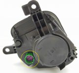
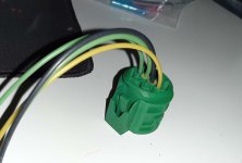
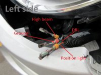
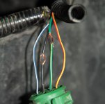
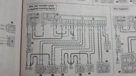
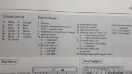
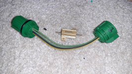
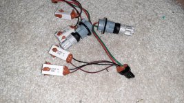
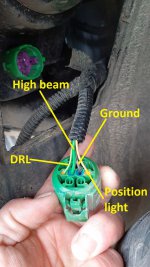
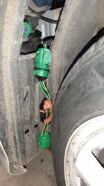
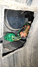
can anybody here help me with the pin assignment if the DRL/hig beam's connector? So in my opinion the little thicker green one, close to the black one ist for the high beam, black is common ground. But I´m not sure with the thinner green one and the yellow one, which is for DRL and which for position light??

Thanks a lot!
 

Attachments

  • Fernscheinwerfer.jpg
    Fernscheinwerfer.jpg
    80.9 KB · Views: 210
  • connector.jpg
    connector.jpg
    81.2 KB · Views: 24
So it should be possible using a meter and the respective lamp holder inside the cluster to work out which pin does what ?
From the book,
Black ground/negative
Yellow/black stripe DRL feed right hand side, green/yellow stripe left hand DRL

Green/yellow stripe right hand side light, yellow/red stripe left side light

Note there is one wire colour(green/yellow) on each side with the same colour but has different functions!
 
Hello John,

first of all thanks for that information. Surely I could have measured it with a meter, but I was asking here hoping that somebody knows it. As with the Abarths relatively big tires and lowering, you need to at least jack up the car to get access and work to some extent at the connector, better remove the complete wheel. It´s winter, dark and cold...honestly said I wanted to avoid this and create the load adapter on the desk.

Basically I want to do the same like this guy https://www.fiat500owners.com/threads/led-drls-resistor-mod.15698/ but he did for an US model (with turnlight instead of hig beam located in there) and I don´t want to solder on my original wiring harness, due to the fact the vehicle is quite new and an I don´t want to loose guarantee....
 
Last edited:
So this will be the assignment according to your information for the left side:

attachment.php


And it fits also to the posting of the guy who did this to his US-model.

attachment.php


But what I don´t understand is, why Fiat didn´t use the second of the two inner pins for the high beam, as they are bigger and so can handle higher current? That the ground pin was one of the inner pins was clear to me, but why they connected the DRL to it? DRL is only 21W, high beam is 55W....for US models it´s not a problem as instead of the high beam, it has only to handle the indicator.
 

Attachments

  • L7sog.jpg
    L7sog.jpg
    171.6 KB · Views: 2,442
  • wiring02.jpg
    wiring02.jpg
    75 KB · Views: 2,620
Hello John,

please don´t misunderstand me, I didn´t want to question your post, I was totally believing in it. I was only wondering why Fiat did it this way. That´s all.

You can clearly see the inner pins are bigger.
 

Attachments

  • Delphi_01042017_17260805-1162947.pdf
    218.2 KB · Views: 37
Hello John,

please don´t misunderstand me, I didn´t want to question your post, I was totally believing in it. I was only wondering why Fiat did it this way. That´s all.

You can clearly see the inner pins are bigger.

No problem just thought this would make it as clear as possible to help you, if you need the high beam wiring image let us know ?
 
No thanks, I think the high beam wiring is not necessary. I now got the male socket housing, only waiting for the pins...then I can start assembling the adapter. Female socket is no problem as it is offered already with cables as repair kit for the wiring harness on ebay and co. .
 

Attachments

  • TFL_adapter_3.jpg
    TFL_adapter_3.jpg
    230.1 KB · Views: 44
  • TFL_adapter_2.jpg
    TFL_adapter_2.jpg
    198.7 KB · Views: 19
Last edited:
Yes I want fit LEDs for DRL, but I want to be able to remove everything without remains. So no mods to the original wiring harness. First I was trying fit everything inside the beam, but there is not so much space left, as the high beams are already also LED and the resistors became quite hot and I also didn´t wont to cut the rubber cap to keep then outside. In addition the aftermarket 7440 sockets didn´t fit good in the beam...so I went for this solution.
 

Attachments

  • TFL_adapter_1.jpg
    TFL_adapter_1.jpg
    244.2 KB · Views: 26
Last edited:
Yes I want fit LEDs for DRL, but I want to be able to remove everything without remains. So no mods to the original wiring harness. First I was trying fit everything inside the beam, but there is not so much space left, as the high beams are already also LED and the resistors became quite hot and I also didn´t wont to cut the rubber cap to keep then outside. In addition the aftermarket 7440 sockets didn´t fit good in the beam...so I went for this solution.

If you use several resistors in parallel then they will not get as hot and are smaller but you have more of them ?
 
For the "inside solution" I used two 33Ohm / 10W ceramic resistors in parallel. For the adapter cable I will assemble now, one 15Ohm / 25W resistor with metallic housing that is able to handle 12,5W @ 25°C beeing mounted free air.

https://www.vishay.com/docs/30201/rhnh.pdf


Should be enough, but to be on the safe side I will attach a small additional heat sink to it.
 

Attachments

  • K-hlk-rper-25mm-x-25mm-x-5mm-Mit-3-Mt-B-nder.jpg
    K-hlk-rper-25mm-x-25mm-x-5mm-Mit-3-Mt-B-nder.jpg
    53.4 KB · Views: 62
So since today I know, that the Haynes manual is not valid for my car. Is it due to the fact it´s a face lift vehicle (year 2020)? Or is the plan in Haynes manual only for US models? So my colours are different, gren-yellow is DRL, thick green is high beam black ground, and yellow is position light.
But in the end it worked without an error message in the dash.
 

Attachments

  • Scheinwerferadapter_17_beschr.jpg
    Scheinwerferadapter_17_beschr.jpg
    235.9 KB · Views: 25
  • Scheinwerferadapter_21.jpg
    Scheinwerferadapter_21.jpg
    224.1 KB · Views: 65
  • Scheinwerferadapter_10.jpg
    Scheinwerferadapter_10.jpg
    199.6 KB · Views: 51
  • Scheinwerferadapter_11.jpg
    Scheinwerferadapter_11.jpg
    184.9 KB · Views: 68
  • Scheinwerferadapter_12.jpg
    Scheinwerferadapter_12.jpg
    204.9 KB · Views: 40
  • Scheinwerferadapter_18.jpg
    Scheinwerferadapter_18.jpg
    185.1 KB · Views: 65
Back
Top