17717052334_1044bd2216_b.jpg

900 Bluebell the 900e Amigo

Introduction

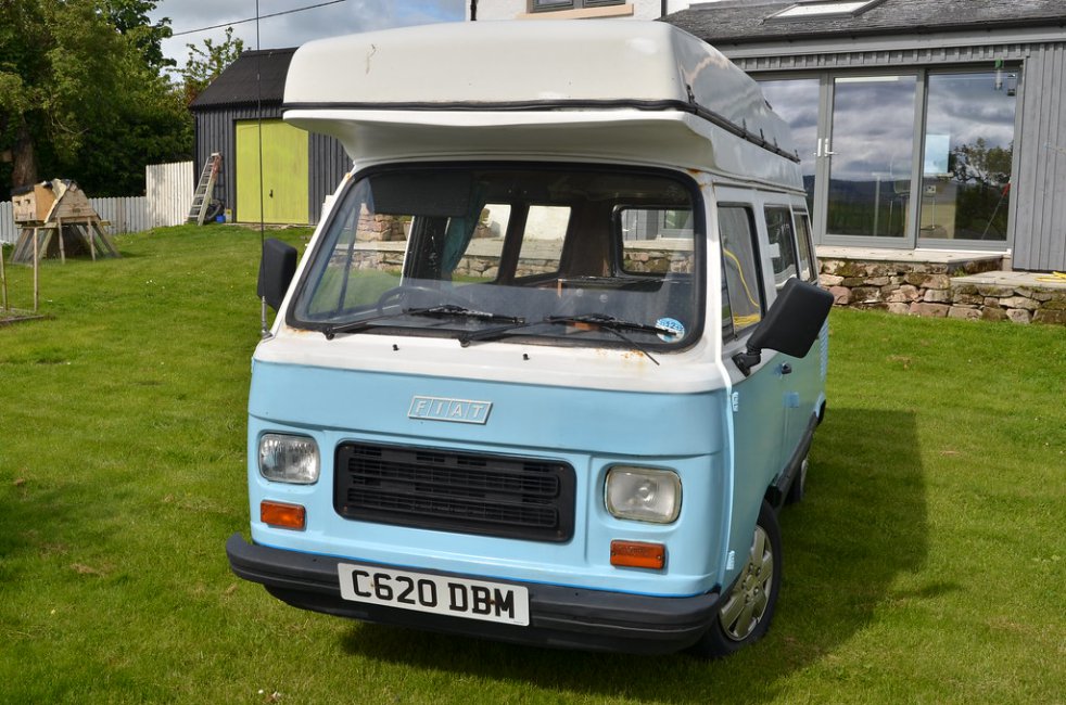
We have just taken on the ownership of this camper from Kelly and Karl and hope to have it on the road within the next six months.
17717052334_1044bd2216_b.jpg
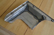
DSC_6177 by Peter Thompson, on Flickr
Not only is it a really lovely vehicle, it was also a pleasure to buy it from such a genuine and really nice couple. There was a huge amount of interest in the sale and I am really appreciative that I was favoured to be the buyer ; so many thanks Karl.:)
18335728502_1005bcd374_b.jpg
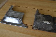
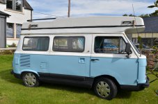
DSC_6176 by Peter Thompson, on Flickr
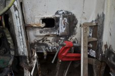
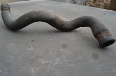
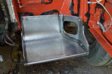
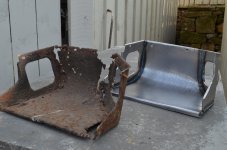
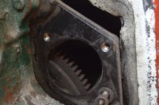
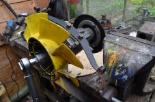
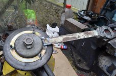
There is a certain amount of essential welding to do underneath, which will add to the welding that has been done in the past. It is currently pretty solid underneath but not as pretty as it could be. I hope to tidy as I go and then work around the bodywork. This has signs of a lot of filler and there is rust poking through in places, but it looks like we will be able to get using it soon.
There are a number of mechanical issue but nothing too onerous and it starts and runs really well.
So a rolling restoration to usable standards.
I just need to get the roof open now!
Watch this space as I document my progress.
Hi
I've finally found the engine number - top left above the timing chain cover as suggested. It is quite faint and had a thin layer of grime over it hence why it was easily missed.

Stamped above the engine number (original by the way) is 100 GF .000 - so the GBC block casting number ties in with what had previously been suggested about most of the later blocks being stamped GBC regardless of where they ended up.

Reading the Haynes manual the GF engine has a 7.9:1 compression (the GBC is 9.5:1). From what I've read elsewhere on the Internet the lower compression should make it more compatible with unleaded petrol - less risk of pre-detonation etc.

If correct (can anyone confirm?), I'm happy to live with fewer horses in favour of the ease of being able to fill up at the pumps without worrying about additives etc.


based on this additional info. as i understand it.

100gbc engine castings when supplied in 900t when new will have 100gf on the engine stamped number above the timing chain and also the head will have 100gf cast in the cylinder head by the exhaust.
100gbc engine castings when fitted in coupes from new will have 100gbc stamped by the engine number and cast into the head.

let me have a look at my engine that didnt seem to perform like a 100gbc should and i will get back to you. this might be the end to my mystery. lets see
 
Pete, you are correct 're pump spindles... after first failure, I had a new unused 3 bolt pump, and we rescued the pump by using the 3 bolt spindle.
Gary, my 84 pandora been running on unleaded fine for last 5yrs,no linking or starting difficulties. In that time it's done thousands of miles all within the speed limit!
 
I'm still waiting for some of the parts for the water-pump and I've made a repair to the casing I damaged on removal by using epoxy-adhesive and a tailored steel plate to strengthen it. A big package of mainly rubber-based parts arrived whilst I was on holiday. So I could make a decent start on the front suspension, amongst other things, but I must first get the engine back together.
My acid-bath did its stuff on the radiator-shroud whilst I was away and it's left with a thin film of iron-phosphate and just needs priming.
The new timing-chain is a really good fit in comparison with the old one....all the sagging has gone and I've since removed the engine-sump so that I can replace the timing-chain cover now that I've fixed the studs back in properly.
 

Attachments

  • FER_9651.JPG
    FER_9651.JPG
    5.1 MB · Views: 96
  • FER_9654.JPG
    FER_9654.JPG
    4.6 MB · Views: 82
  • FER_9655.JPG
    FER_9655.JPG
    4.8 MB · Views: 103
  • FER_9657.JPG
    FER_9657.JPG
    5.5 MB · Views: 62
I'm still plodding away at sorting everything in the engine bay which led me to doing a few pieces of welding which I couldn't get at until the radiator was removed.
I've also pulled out the metal pipework that runs back to the heater and I'm not decided on how to replace it. It could easily done using copper pipe and fittings like Vin but I might extend it so as to remove the need for the complicated rubber pipe pictured, which conveys the hot water from the thermostat housing to the solid heater-pipe as I am unable to find a new replacement. I might even do it in plastic PEX pipe because this is fairly flexible and I have a load left over from plumbing the house; the only issue there is that the fittings are very bulky.
Every day I sort out a few details of the engine-bay and amongst other things, today I coated the pump-body and thermostat housings in clear epoxy paint; at the price they cost new it is worth protecting them from corrosion for as long as possible.
I've also got the sump and other metal parts soaking in the bath of phosphoric acid so that by the time the pump is rebuilt and ready to fit everything should be de-rusted and ready for use at the same time.
 

Attachments

  • FER_9659.JPG
    FER_9659.JPG
    4.6 MB · Views: 76
  • FER_9661.JPG
    FER_9661.JPG
    4.3 MB · Views: 99
Last edited:
There's been quite a bit of work to be done on my 500 which has brought the welder out of storage and taken me away from the van for a week. Whilst in the mood for metal-shaping and melting I thought it was time to make a start on the engine undertrays. There aren't many pieces of this left intact and the most original remaining item is a backwards-facing scoop which directs the hot air towards the rear of the vehicle; you can see new and old side by side.
I've had guidance from an excellent blog-page here: https://spannerdude.wordpress.com/pandora/the-blown-diffuser/

But I'm not as interested in emulating the original construction so possibly found an easier way to make it. It's so good working with entirely new steel when it comes to welding. The item did take about three hours to cobble-up and I did the final tacking together with the three component parts bolted in-situ so that it would end up a good fit.

Obviously I'm very pleased with this part because it would surely be impossible to obtain a new one. The next item will be the main undertray.
 

Attachments

  • FER_0499.JPG
    FER_0499.JPG
    4.3 MB · Views: 89
  • FER_0501.JPG
    FER_0501.JPG
    4.1 MB · Views: 332
The main engine undertray supplied with the van was a simple piece of sheet-steel which was roughly cut to fit and bore no ressemblance to the correct one. So I consulted the web-pages referred to previously for clues.

I made something similar to fit;. It is relatively straightforward in shape but takes quite a bit of work to get the geometry and alignment right.

The original section of tray which fits above the exhaust silencer had been patched-up with a combination of aluminium/bitumen tape or flashing and some rough fibreglass. It was simple to make but involved a fair bit of butt-welding as it was a bit complex for me to simply beat into shape out of one or two pieces. If there is sufficient clearance I may supplement this with some spare aluminium heat-shield that I've been keeping for such a purpose.

It looks like the original trays were fixed with self-tapping screws and matching captive "nuts". As the new ones are tailored to fit I was able to weld M6 nuts so that it can all be secured using some of my surplus stainless, hex-socket screws.

I still need to get some rubber so that I can rivet a sealing-flap where the undertrays meet the engine sump, but I'll do that when it's all in-situ and the engine is fully assembled.
 

Attachments

  • FER_0820.JPG
    FER_0820.JPG
    4.1 MB · Views: 79
  • FER_0819.JPG
    FER_0819.JPG
    4.2 MB · Views: 75
  • FER_0817.JPG
    FER_0817.JPG
    3.8 MB · Views: 72
Have you found a supplier for the rubber sealing flaps yet?
(It's on my to do list but haven't looked yet.)

With the sealing flaps are they supposed to touch the engine to create a full seal or just get close? I can't tell with Connie's old under trays, as they have been repaired several times and left a gap - this could have been wear or meant to be that way.

Would you use rubber to seal around the exhaust as well?

Also, is the only purpose of the under trays to stop heat from the radiator getting back into the engine bay? If yes, I'm hoping that the ducting that I've added to Connie will remove the need for a tight fit between the engine and under trays - or remove the need for them completely (other than the ones used for the ducting).


I'm not even going to try to find the original sealing-rubber although I've some fragments left. Something like this should work:

https://www.ebay.co.uk/itm/Medium-B...m19fe92bb7e:g:XwQAAOSwhcJWLdOJ&frcectupt=true

It looks like they were tightly against the sump but not close to the exhaust. I suspect that the idea was that the engine-bay should be as tightly sealed as possible from below so as to encourage all the air to enter via the side-louvres. But that's a bit of a futile aim given that sealing around the exhaust was not attempted.
I have no experience of VW Beetles but I've read that they have a well-sealed engine-bay which has a significant effect upon cooling so I'm going for maximum airtightness to below.
 
This post contains affiliate links which may earn a commission at no additional cost to you.
For the last four weeks I've been anxiously waiting for the repair kit for my water-pump, which has been holding up the engine refurbishment. Today I found that it had been delivered ages ago whilst I was in Italy and was sitting in a pile of logs in the garden. Everything was waiting for assembly so it followed that I should assemble it.

It's quite a tricky to work out the correct order to fit all the pieces but after a lot of dry-runs and faffing about it's now in one piece again.

It's a relief to have saved the hundreds of pounds that a refurbished or new pump would have cost me and good to know that this very important component functions like new again. OK, it doesn't look like new, but that's not my way of doing things, but with new seals and bearings, new gasket, keys, re-threaded shaft and new nuts, some epoxy repairs to the casing and clear epoxy paint to protect the aluminium, it should be good for another 35 years.:)
 

Attachments

  • FER_0864.JPG
    FER_0864.JPG
    4 MB · Views: 74
  • FER_0866.JPG
    FER_0866.JPG
    3.4 MB · Views: 93
  • FER_0868.JPG
    FER_0868.JPG
    4 MB · Views: 71
I had a look at the alternator and decided it was worth stripping it down because the bearings felt a bit rough. I also found that the brushes were worn unevenly, but visually, everything else looks good. I'll have to test the electrical parts and then it will take a bit of detective work to track down the spares I will need.

The undertrays etc. all now have a shiny coat of Tesco paint and I'm now homing-in on a load of little jobs that have come to light as I stripped it down. One of the stud-threads for the starter-motor has obviously been stripped for ages and another was looking dodgy, so both now have shiny, new helicoils fitted. I'm not sure if all three fixings were originally studs because non-original setscrews were fitted to the damaged holes. I might as well refurbish the starter-motor whilst I'm here so that's the next job.
 

Attachments

  • FER_0877.JPG
    FER_0877.JPG
    8.7 MB · Views: 76
  • FER_0875.JPG
    FER_0875.JPG
    8 MB · Views: 89
  • FER_0872.JPG
    FER_0872.JPG
    8.8 MB · Views: 87
I've had a successful week of achieving bits and pieces. I worked out that the roof hinges which I had condemned were just slightly distorted; so I tweaked them. One is broken but I'm adapting a new steel one to fit.

2vkev53.jpg


They fix into fibreglass and the original rivet-holes were damaged, but then I realised that the glass was reinforced with an aluminium plate. So I've tapped into that, fitted Helicoils and the hinge problem is over. A few holes wouldn't co-operate so I've obtained some excellent rubber inserts with brass threads at the bottom which act as hollow-fixings.

I gave up trying to find new replacements for the two heater hoses of which the hot water feed is a real one-off. So I've cleaned them and then wrapped tightly in amalgamating tape, which bonds to make a leakproof and protective layer. I've used this as chafing protection on the two new solid pipes I've fitted where they pass through the "chassis". I've copied Vin 's idea but adapted it to use a couple of 15mm compression fittings I had lying about and I fitted solder-ring fittings to the ends which gives me a nice grippable spigot for the rubber pipe.

zmksvn.jpg


2gvsh28.jpg


The alternator is rebuilt and fitted. The slip-ring was a perfect fit and although fittng it to the shaft and solder it was nerve-racking it's another job well done.

23ogo6.jpg


111ruc5.jpg


So the engine is coming together now and I have the carburettor in bits (so simple :D) and the derusted fuel-tank's ready to seal inside and paint outside. I will be going to town with the prep because the tank is such a rare item and so easily corroded, being just behind the rear wheel splash-zone.

It's funny with the restoration, that I go from being stymied by lack of inspiration and ideas of how to go forward to a situation where there are loads of things to fit and it's all fallling into place; it really is like a jigsaw-puzzle.:D
 
Last edited:
Before you refit the fuel tank I highly recommend cutting an inspection hatch in the van floor directly above the sender unit. This will make refitting the fuel lines much easier and if you need to change the fuel sender in the future you won't need to drop the tank.

Unfortunately, I didn't do this and I'm now faced with having to drop the tank again to make sure the fuel line connections aren't leaking. There is a strong smell of petrol in the van when the engine is running and the smell appears to be coming from the fuel tank area. However, there is no obvious fuel spillage on the ground but I need to check to make sure and eliminate the risk... I don't want all my hard work going up in flames.
 
Before you refit the fuel tank I highly recommend cutting an inspection hatch in the van floor directly above the sender unit. This will make refitting the fuel lines much easier and if you need to change the fuel sender in the future you won't need to drop the tank.

Good advice which I will follow. I am now ready to paint the tank and seal it but have encountered a hitch as the van has an incorrect carb without the return pipe for fuel. I do have a spare which looks more likely to be the right one but as the van is converted to a flat air-filter I want to avoid the effort of fitting the big, remote, cylindrical job.

I've been held up by the diversion of sorting out the radiator and coolant pipes. I also found I had a leak from the gasket and one of the M10 setscrews securing the water-pump. So forget the gasket and I will be using my old Permatite favourite instant gasket material. I've also got some fibre-washers which will go under the steel-washers and I hope this will stop the leak.

Taking the pump off allowed me to try to modify the cooling-fan shroud to stop it catching. One of the things I tried was to move the position of the fan on its spindle slightly, which didn't work. Ithink it has just been mishandled and needs some carefull bending. :eek: I wasn't 100% happy that the securing nut was tight so by using a spare pulley-spacer welded to a handle I was able to lock it all up in the vice and put on the full torque. Without this I had to hold the fan itself or use another spanner on the opposite nut; this is not conducive to accuracy. You can see that my special tool is setup for the same job on my Fiat 500.

With a bit of luck I'll have the thing running again by the weekend.:)
 

Attachments

  • FER_1776.JPG
    FER_1776.JPG
    2.4 MB · Views: 60
  • FER_1777.JPG
    FER_1777.JPG
    2.2 MB · Views: 79
I finally got all the loose ends sorted and fired-up the engine. It kicked into life the moment that fuel got through to the carb and quickly settled-down with no further adjustments needed and a nice healthy charge from the alternator

[ame]https://youtu.be/UNEqxzMuaEU[/ame]

So now it needs the air-filter assembly and I have to work on painting the fuel tank and its location under the van so that I finally have a plumbed-in fuel system. Although the engine was one of the high points of the van as collected, because it did actually work. But the external refurbishment revealed so many things which were on their last legs and it now sounds smoother and has instant starting.

There is an annoying leak from the water-pump despite this having new seals etc., but I hope this just needs time for the carbon-seals to settle down.
 
The next time you fire her up any chance that you could time how long it takes for her to get up to normal operating temperature? Ideally with no more choke than absolutely needed and no load/revving.

The reason I ask is that I'd like to get a bench mark to compare Connie's warm up time with (now she has an electric fan). Weather permitting, I'll time Connie's warm up time this weekend and share.

I'll give that a try but first I'll need to temporarily wire in the gauges. I think your warm-up will be the same as ever because it will be dependent on the thermostat. I've put a new one in and it takes ages before the water actually starts to flow to the radiator and by that time it must be up to optimum temperature.

Is your fan on permanently or do you have a sender-switch. With a good thermostat and if the fan is very efficient you might not need it running all the time.
 
I think your warm-up will be the same as ever because it will be dependent on the thermostat.

Good point about the thermostat, I'd forgotten about that.

The electric fan has a sensor stuck to the top of the radiator, just above the fins. Ideally, it should be inserted between the rad core fins but it is to long (the chap a Merlin Motorsport recommended the alternative position).

The sensor links to a control box, this gives the temperature readout and you can set what temperature you want/need the fan to come on/off. At the moment it's set at the default 85C which puts the dashboard temperature gauge steady at mid-way.

Note: As the sensor is not in the optimal position it will be reading a little on the low side - the 123-Ignition Conversion also has a temperature gauge which reads different again.

I've hooked up a light on the dashboard to tell me when the fan is running. I'm hoping that the ducting I've put in will help draw the hot air out the back reducing the need for the fan to be running (when moving forward). I won't be able to test this theory until the van is back on the road though.
 
I can time it to when thermostat opens: you system sounds good.[emoji6]
Good point about the thermostat, I'd forgotten about that.

The electric fan has a sensor stuck to the top of the radiator, just above the fins. Ideally, it should be inserted between the rad core fins but it is to long (the chap a Merlin Motorsport recommended the alternative position).

The sensor links to a control box, this gives the temperature readout and you can set what temperature you want/need the fan to come on/off. At the moment it's set at the default 85C which puts the dashboard temperature gauge steady at mid-way.

Note: As the sensor is not in the optimal position it will be reading a little on the low side - the 123-Ignition Conversion also has a temperature gauge which reads different again.

I've hooked up a light on the dashboard to tell me when the fan is running. I'm hoping that the ducting I've put in will help draw the hot air out the back reducing the need for the fan to be running (when moving forward). I won't be able to test this theory until the van is back on the road though.
 
Back
Top