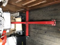
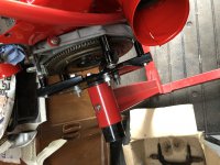
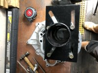
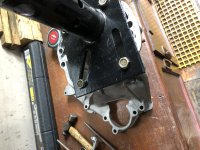
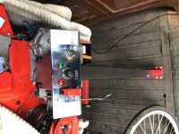
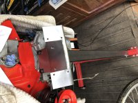
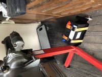
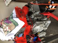
Greetings, Have any of the great and good on here a picture or pictures of their engine test stand. By that I mean one where you can start the engine and run it.
I have been wondering if I could adapt a gearbox bellhousing for the starter motor and bolt an engine onto it?????? I don't want to run it on the floor as knowing my luck the damn thing will decide it's going to go walkabout out of control Anyone got any idea's???
Ian.
I have been wondering if I could adapt a gearbox bellhousing for the starter motor and bolt an engine onto it?????? I don't want to run it on the floor as knowing my luck the damn thing will decide it's going to go walkabout out of control
Anyone got any idea's??? Ian.