Technical 704cc 'HOT' Engine Build

Currently reading:
Technical 704cc 'HOT' Engine Build

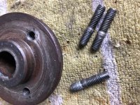
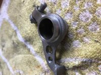
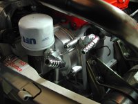
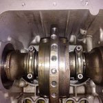
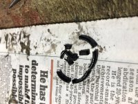
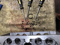
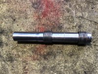
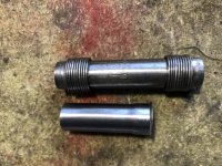
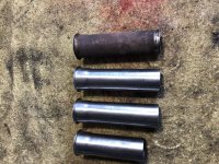
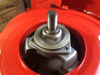
Greetings, work at the swop shop continued today for an hour or two sorting another problem with the studs on the alternator fan belt hub, two are just acceptable, but one is beyond saving (n)(n) so I've sorted a replacement hub from mr E. Bay and the remaining studs and hub can go into the spares box (y)(y)(y)
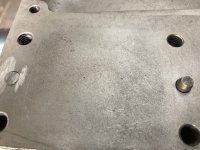
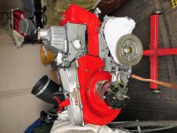
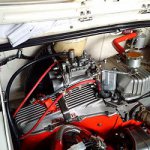
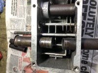
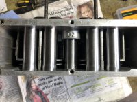
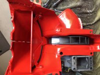
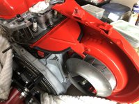
The fan housing was another trial as you would think that 'if it comes off another engine it will fit on the new one' ??
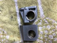
NOT!!!:mad::mad::mad: What a game it was getting all 9 bolt holes lined up !!! I began to think that I had done something wrong during the build so far - it just would not line up. I then thought what's the other engine like??? Aha !!! the little lower location dowl for the alternator mount had been removed - very cunning (y)(y)(y)
So I just did the same - carefully, and hey presto it all fell into place all bolt holes lined up :worship::worship::worship:
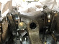
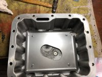
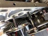
next the sump mod and the timing cover - fingers crossed!!
Ian.
 

Attachments

  • IMG_0507.jpg
    IMG_0507.jpg
    148.3 KB · Views: 46
  • IMG_0508.jpg
    IMG_0508.jpg
    107.1 KB · Views: 46
  • IMG_0509.jpg
    IMG_0509.jpg
    137.7 KB · Views: 63
Those studs on the pulley are peined over on the inside after fitting at the factory so not easy to remove.
 
If your problem does turn out to be the cam-shaft bush, "Passione" (and I expect that the're not the only people) have repair bushes for sale--part number:--MOT33C. Basically, you ream out the original bush and fit the replacement.

Hi Tom, I've found the problem. When I removed the sump today to effect the anti-surge plate fitment I found a crankshaft core plug sitting in the bottom :mad::mad:
I did not find any ferrous metal on the magnetic plug or inside the timing case and there is not obvious signs of damage, but I will strip it down and inspect as well as getting the core plug welded in this time (y)(y)(y)
Ian.
 

Attachments

  • IMG_0510.jpg
    IMG_0510.jpg
    105.9 KB · Views: 41
Greetings, After the core plug shock I intend to get them welded in as with my BIS crank, then got on with the oil baffle plate fitting. Simple enough job to drill the cast-in alloy posts on the bottom of the sump and then run an M5 thread into them. The main problem was flushing out all the swarf and getting a clean result. A spot of lock tight on the bolts and its job done. I'll fit the sump tomorrow without a gasket to help brace the crankcase just a dab of sealant and Bob's your uncle !!! more later.
Ian.
 

Attachments

  • IMG_0511.jpg
    IMG_0511.jpg
    103.8 KB · Views: 32
  • IMG_20181203_142345.jpg
    IMG_20181203_142345.jpg
    2 MB · Views: 46
Wow Ian, you were mighty lucky that it didn't totally fall out whilst the engine was running fast! Have you had the core-plugs on your 'hot engine' crank 'tigged'? If you haven't, I would suggest that you do; the very minimal extra weight should not have any noticeable effect on the crank balance.
It will be interesting to hear what the oil pressure comes out as when the crank has been repaired.
 
Right break out the Vaseline!! :eek::eek::eek:
No silly, I need it to pack my oil pump prior to assembly it gives the pump something to suck on when drawing oil from the sump for the first time (y)(y)(y)
I have rebuilt the oil pump and spin-on filter adaptor with all new seals, but I have found a potential source of conflict between parts inside after fitting the timing case.
As is known I have elected to use a timing gear set rather than the normal cog and chain arrangement. but, having used special camshaft bolts and washers found that the internal clearance is very tight between the oil pump bolt heads and the rear of the pump idle gear tube and the camshaft bolts. The mod to cure this was to simply use set screws to retain the pump and to remove (grind down) the small protruding lip from the back of the pump. This gave the required clearance for everything to turn freely. The sump went on ok with the pick up extension compressing the spring. More later.
Ian.
 
Greetings All, sorry for the delay but work and and a visit to the outlaws in Ireland have conspired to delay me with the build. (n)(n)
I can now announce that the 'Bit-part' engine has been fitted and after a short period of non starting traced to a faulty condenser is now running. (y)(y)
initial findings show a lumpy idle, but this is expected with a hotter cam and a lightweight flywheel, crankshaft and conrods. As soon as the rpm rises above some 1000 to 1500 rpm (future analysis will determine the exact point) the engine stops shaking and becomes very smooth with the response to throttle quite sensitive in nature. The running in will continue when weather permits. I will summarise all the work done area by area when I have time. More later.
Ian.
 
Ian, my recently installed "performance 700cc" (that's how the seller described it) is probably very similar to your build, and here's how it's running to confirm this behavior is "normal." I've got aggressive cams, higher compression, about 700cc, a Panda head, a Dell'orto DHLA 40, and a 123 electronic ignition. Now that mine is broken in, I'm experiencing the same- lumpier idle until quite smooth over 1100-ish rpm, EXTREMELY sensitive throttle, and quite a lot more power. Keep up the great work! I've been quiet a month or so due to holiday, but I'll make a big update post to my thread soon. ;)
 
OK Folks, to summarise the build to this point I'll start at the top and work down (y)(y)
The Rocker rail is a refurbished item fitted with lightened rocker arms to reduce weight with new 7mm adjusters and a set of steel mounts to increase the rigidity of the assembly. The valve springs are new, but of standard performance. The valves have been reground and cleaned up, again remaining with standard sizes in the panda head of 34mm IN and 28mm OUT. New valve guides and seals have been fitted.
The head had already been skimmed to 34.2 cc capacity prior to my ownership this has been left as is. The head has been repaired between the valves on both cylinders although only one was cracked, the repair adds strength.
new steel plug inserts have been fitted too as the alloy threads wear quickly. Porting and polishing has been carried out to intake and exhaust tracts matching the inlet manifold and exhaust elbows. The previous upper short pushrod tubes have been removed and the lower hole has been opened up to allow the use of two part VW adjustable pushrod tubes, these have also been cut to size. The larger VW tube oil seals have also been used. Due to the skimming of the head the pushrods themselves have been shortened to maintain the all important rocker angle at half of cam lift. A 40/80-80/40 Cam is used giving a theoretical 11.55mm of lift at the valve using a rocker ratio of 1.5 but this has been adjusted to give 10.95mm lift allowing for a clearance of 25 thou between the valve spring coils at max lift, if the clearance is less you may get 'binding' and thus broken springs. The carb is a Solex C35PHH 10E which is slightly smaller and much lighter than the equivalent Weber or Dellorto, a one-piece low level manifold has also been used to give good clearance above. The final Carb setting can be found in this thread after the rolling road set up.
The only possible improvements I can see being carried out at a later stage is to enlarge the inlet valve to 35mm
Gas flowing could also be completed, but I consider the cost of a full flow-bench mod only necessary if you are going to race the engine. More later.
Ian.
 

Attachments

  • DSCN2496.JPG
    DSCN2496.JPG
    11 KB · Views: 1,066
  • IMG_0211.jpg
    IMG_0211.jpg
    24.9 KB · Views: 30
  • IMG_0212.jpg
    IMG_0212.jpg
    16.2 KB · Views: 1,070
  • IMG_0215.jpg
    IMG_0215.jpg
    13.1 KB · Views: 1,068
  • IMG_0241.jpg
    IMG_0241.jpg
    37.3 KB · Views: 36
  • IMG_0238.jpg
    IMG_0238.jpg
    34.7 KB · Views: 34
  • IMG_20180420_192057.jpg
    IMG_20180420_192057.jpg
    14.1 KB · Views: 1,070
  • IMG_20190124_154849.jpg
    IMG_20190124_154849.jpg
    20.2 KB · Views: 1,076
Greetings, To continue. The 80mm bore barrels arrived in an un prepared state and had to be checked for true before a final hone. The pistons are new standard BIS with new ring sets. The rings have been adjusted for barrel fit (or grip) and the gap edges have been rounded off to prevent scratching the bores. The question of correct deck height and thus compression ratio took a while to work out, with the correct squish band adjusted using a selection of spigot base support plate, copper head gasket and eventually the removal of some 1.5cc from the piston top to get the figures right. We finally arrived at a squish of 45 thou and a C/R of 10.5:1.
I used my previous timing case cover with the integral Nanni spin-on filter adaptor, the oil pump has been modded to suit. The filter is a low level UFI item from a Ducati bike engine. This gives plenty of room above for the exhaust manifold. The Cam timing is achieved using a D'Angelo gear set rather than the ubiquitous chain and cog
set up. This allows perfect accurate timing. The special bolts used on the Cam wheel caused a slight problem in that they just contacted the back of the oil pump, but this was resolved by using set screws to hold the pump and the removal of 3mm from the pump rear. I might add that this surgery does not affect the operation of the pump!!!
more later.
Ian.
 

Attachments

  • DSCN2466.jpg
    DSCN2466.jpg
    545.6 KB · Views: 35
  • IMG_0247.jpg
    IMG_0247.jpg
    12.5 KB · Views: 981
  • IMG_0218.jpg
    IMG_0218.jpg
    33.5 KB · Views: 30
  • IMG_0216.jpg
    IMG_0216.jpg
    31.5 KB · Views: 34
Moving onto the bottom end, All the rotating components -
(oil filter - crankshaft - flywheel - clutch pressure plate) have been balanced. The main bearings are a hi quality from Italy. If anyone uses these bearings they MUST check the crankshaft end float for the correct measurement as it tends to be tighter than normal. The oil pick up has been extended and the 4Ltr sump has a baffle plate. The sump is fitted without the usual gasket and only a silicon sealant is used. This promotes extra stiffness in the lower crankcase area. I have found that an extra stiffening plate is available from Europe, it fits between the bottom of the crankcase and the sump. BUT, due to it's shape it will prevent the splash lubrication of the little end unless the conrods are drilled. my set of Maxspeeding rods are not drilled. This may be a future job. The clutch and pressure plate are an uprated set from MBG. The rods are held with ARP 2000 bolts.
One thing I will recommend is that if anyone is modifying a 500/126 engine they MUST get the crankshaft core plugs welded. I have just a lucky escape with one of mine in the other engine, if I had been pushing on the engine would have been trashed :eek::eek:
More later.
Ian.
 

Attachments

  • IMG_0255.JPG
    IMG_0255.JPG
    66.4 KB · Views: 29
  • IMG_20181203_142345.jpg
    IMG_20181203_142345.jpg
    2 MB · Views: 32
  • IMG_20181220_140613.jpg
    IMG_20181220_140613.jpg
    9.2 KB · Views: 951
  • IMG_20190226_110612.jpg
    IMG_20190226_110612.jpg
    14.4 KB · Views: 952
  • IMG_20181027_135424_hdr_edit.jpg
    IMG_20181027_135424_hdr_edit.jpg
    1.4 MB · Views: 33
  • IMG_0511.jpg
    IMG_0511.jpg
    103.8 KB · Views: 32
  • IMG_4538.JPG
    IMG_4538.JPG
    4.6 MB · Views: 32
  • s-l64.jpg
    s-l64.jpg
    1.9 KB · Views: 952
Greetings All, just to finish this part of the thread with the exhaust system. I'll be fitting the same stainless four-part system that has had the elbows ported to the head exhaust ports. The system is from CSC Marmitte, I will say that to improve things even more it would be better to have a system that has equal length down pipes so that there is no gas pressure differential. You pay your money and take your choice !!(y)(y) I'll follow later with running in and a rolling road run.
Ian.
 

Attachments

  • IMG_20180113_191555.jpg
    IMG_20180113_191555.jpg
    16.2 KB · Views: 814
Greetings, This thread has gone a little quiet of late as work with the "Hot" engine is now on the back burner because I need to rebuild the 'other' engine due to a core plug blowing out.
Have stripped the unit and checked all the bearings I am happy to say that I have got away with it(y)(y)(y) probably due to driving in traffic when the oil pressure died :eek: Anyway the rebuild is going well with little jobs arriving along the way to slow things down - the powder coating of the bambino fan housing took an age and needing to drill and tap the new 3 1/2 Ltr sump for an oil temp sensor for another !!! Waiting for parts (it's the wrong time of year) is another patience sapping problem (n)(n)(n)
But, I have been looking into a certain problem with the Panda head and trying to come up with a cheap way of curtailing the oil leaks from the fixed (upper) pushrod tubes. In the 'Hot' engine I have used VW tubes that are not cheap and if you factor in the removal of the old fittings and the engineering to open up the lower hole for the vw items the cost outweighs the benefit in my opinion.
So, I have decided to remove the remaining upper tubes and replace the oil seals in the head. I am lucky because I still have the old tubes to enable me bash out the fitted ones - carefully !!! I really am hoping that this will cure the problem as the oil loss can be prodigious, I'll update things as I go after cleaning and polishing everything - removing the old hardened seals is a faff too (n)(n)(n) Happy New Year to All.:D:D:D
Ian.
 

Attachments

  • IMG_4230.JPG
    IMG_4230.JPG
    2.5 MB · Views: 28
  • IMG_6594.JPG
    IMG_6594.JPG
    2.6 MB · Views: 27
  • IMG_5887.JPG
    IMG_5887.JPG
    2.4 MB · Views: 25
Ye Gods!!!!! What a job that was (n)(n)(n)
Getting the upper pushrod tube oil seals out of the head is such a pain I really hope that this work will cure the leaks ????? I think that owners of this type of head will find that the seals will have become hardened and brittle from the cooking they receive over time. :eek::eek: To remove the said items I have obtained a set of picks (Aldi) and although they do the job well the seals break up into small pieces and go everywhere - the cleaning will have to be very thorough. :mad::mad::mad:
Ian.
 

Attachments

  • IMG_9603.JPG
    IMG_9603.JPG
    4.1 MB · Views: 21
Greetings, after the trauma of removing the pushrod tube seals I have discovered that an old toothbrush is great for sweeping all the leftover bits in the grooves away, also I'm not taking any chances with the fit of the replacement seals and will use the 'Dirko' sealant that was recommended to me - it's super stuff and very 'sticky' (if that's the correct word?) I'm pleased with the finish on the pushrod tubes after cleaning and using a harsh buffing wheel to remove all the rust etc, the finish will be short lived though.
(n)(n) One thing I have noticed is that with the original set of short flexible Panda tubes there is a difference in the end fitting. It appears that one end is a much better fit into the base of the fixed tube, with this 'snug' fit I should be able to get away with a simple 'O' ring and use the normal larger seal at the bottom. (y)(y)(y) I don't recall how I put the tubes in last time and maybe, if the wrong way around, this contributed to the oil leak ???
All the very best to Forum members for 2020 if you are already there - Happy New Year - if not yet Happy New Year!!!! (y)(y)(y)
Ian.
 

Attachments

  • IMG_1038.JPG
    IMG_1038.JPG
    4.7 MB · Views: 22
  • IMG_9887.JPG
    IMG_9887.JPG
    2.5 MB · Views: 23
  • IMG_4403.JPG
    IMG_4403.JPG
    4.1 MB · Views: 25
Ian, would it not be possible to fit new 'O' rings into the seal-grooves in the cylinder head? It would be a lot less messy, and if tight enough that you have to use rubber lubricant to insert the top push-rod tubes through the seals, they shouldn't leak---there is no pressure on the seals, just the 'loose'oil floating around inside the rocker cover. The fact that the 'factory' seals were square in section and the new seals will be round should have no detrimental sealing effect; if the new seals are tight both inside the grooves (in the head) and on the push-rod tubes, effective sealing should take place.
 
Ian, would it not be possible to fit new 'O' rings into the seal-grooves in the cylinder head? It would be a lot less messy, and if tight enough that you have to use rubber lubricant to insert the top push-rod tubes through the seals, they shouldn't leak---there is no pressure on the seals, just the 'loose'oil floating around inside the rocker cover. The fact that the 'factory' seals were square in section and the new seals will be round should have no detrimental sealing effect; if the new seals are tight both inside the grooves (in the head) and on the push-rod tubes, effective sealing should take place.

Hello Tom (Happy New Year) after a bit of trial and error I have replaced all of the oil seals with an item of 21x2.5mm I could possibly have used 3.5mm but pressing the tubes back in would need a great deal of force and beyond me.
(n)(n) I did use a small dab of sealant top and bottom too. The 'o'ring set I have (Aldi) has a large enough item for the top of the flexible tubes as well. Let's just hope they don't leak (y)(y)(y)
Ian.
 

Attachments

  • IMG_5067.JPG
    IMG_5067.JPG
    2.9 MB · Views: 23
  • IMG_4366.JPG
    IMG_4366.JPG
    2.4 MB · Views: 24
The 'o'ring set I have (Aldi) has a large enough item for the top of the flexible tubes as well. Let's just hope they don't leak (y)(y)(y)
Ian.


In my experience and hopefully not yours the cheaper 'O' rings
are made ut of really poor rubber and not the better PTFE rubber of some of the more expensive sets and will break down quite quickly :(
 
In my experience and hopefully not yours the cheaper 'O' rings
are made ut of really poor rubber and not the better PTFE rubber of some of the more expensive sets and will break down quite quickly :(

Yes, that may indeed be the case although I did use sufficient sealant too (y)(y) It's a case of wait and see. At least now I know how to remove the damn things, I should be able to whip off the head and replace them all with it in the car.....maybe :eek::eek:
Ian.
 
Greetings, Now that the head is back on I have tried to sort my 'other' fan housing rather that swop back the original three piece part and that's where my 'Baby' problems started (n)(n)(n)
The 'Bambino' two piece fan housing is from a German model 126 and I believe fitted against the late square 126 cylinder head (Not the same as a Panda head) I've had endless problems lining up all the bolts and maintaining fan clearance and at the same time getting the airflow splitter to fit into the head, luckily the Panda head has the same slot in the head fins to accommodate this. But, as the head and cylinders are modified the dimensions are rather askew to put it mildly :mad::mad::mad: So, with a different alternator, fan and housing what do you think the chances are of getting it all on in one ???? ZERO :eek:
The location dowels for the alternator mount have had to come off and all of the housing bolt mountings have had to be 'adjusted' somewhat :bang::bang:
After many fitting and removal attempts I have discovered that my parts don't fit without starting the assembly with the alternator mounting, there is a small amount of adjustment on the housing to alternator mount and this has helped keep the fan clear - so far (y)(y) with all the bolts loose to allow wriggle room the rear half of the housing is on maintaining fan clearance (y)(y)(y) I've had to shim the fan itself, as it would never have fitted otherwise. My pile of 'spare' parts is slowly reducing, but it's not getting easier fitting them :mad::mad::mad:
Ian.
 

Attachments

  • IMG_3779.JPG
    IMG_3779.JPG
    2.3 MB · Views: 50
  • IMG_2986.JPG
    IMG_2986.JPG
    2.4 MB · Views: 59
  • IMG_2843.JPG
    IMG_2843.JPG
    2.7 MB · Views: 31
  • IMG_5345.JPG
    IMG_5345.JPG
    2.1 MB · Views: 28
  • IMG_0850.JPG
    IMG_0850.JPG
    4.5 MB · Views: 26
Back
Top