Technical 704cc 'HOT' Engine Build

Currently reading:
Technical 704cc 'HOT' Engine Build

Morning Al

I understand your theory but if the one hole is the same size as the I/D of the pick up pipe then that’s sufficient?

Rob
I think that the combined area of the holes in the mesh of the intake will be several times greater than that of the suction pipe. So it will be wise to heed Al's F123C advice and be sure to have adequate entry for the oil into that chamber. I remember reading that all sorts of weird and undesirable things can happen in oil which is over-restricted whilst being pumped.

Morning Al

I understand your theory but if the one hole is the same size as the I/D of the pick up pipe then that’s sufficient?

Rob
 
Hi, Ian,

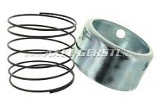
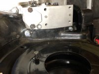
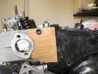
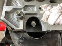
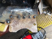
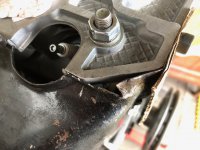
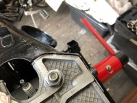
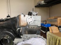
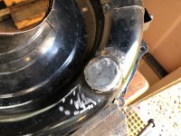
If that extension actually contacts the sump when the sump is in place, I think I'd like to see more holes for the oil to be drawn in - I can only see 1 hole in the pics. Maybe run this by your Engine Man for his assessment?

Normally, afaik, there is usually at least a 6-8mm space between the oil pump pick-up screen and the sump, so this area (6-8 x circumference of oil pick-up screen mm2) would need to be matched by the total area of any holes in the extension.
I've even run engines without the pick-up screen in place to minimise any restriction at the oil intake to the pump - I wonder how much power it takes to suck oil through such small holes, plus it possibly also adds unwanted heat into the oil. But this was on engines that had an anti-drainback valve in the oil filter, idk if it would be safe on the 500?
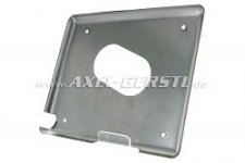
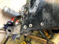
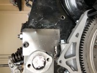
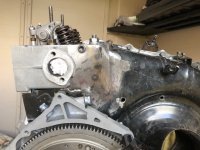
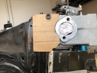
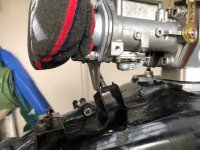
Also, if there is any possibility that fitting the sump will try to push the extension up against the spring pressure, you might need to extend the notched cut-out a bit more.
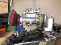
Great workmanship and attention to detail, so far. (y)
Regards,
Al.

Hi Al, the extension had three holes to help admit oil, but I may drill a couple more for safety. I am going to fit an anti-surge plate too and I reckon the central hole in it will be partly covered by the pick-up, it's all in a 4Ltr alloy sump anyway (y)(y)
Ian.
 

Attachments

  • 31822a82c275218757f2854e695b7c25.jpg
    31822a82c275218757f2854e695b7c25.jpg
    8.4 KB · Views: 839
  • c18ebe6ed90743cbfd791214a202d308.jpg
    c18ebe6ed90743cbfd791214a202d308.jpg
    5 KB · Views: 836
I think that the combined area of the holes in the mesh of the intake will be several times greater than that of the suction pipe. So it will be wise to heed Al's F123C advice and be sure to have adequate entry for the oil into that chamber. I remember reading that all sorts of weird and undesirable things can happen in oil which is over-restricted whilst being pumped.


Yes I fully get that but there’s only a certain amount of oil can go up that diameter of the suction tube...........and just put a twist on it further would many little holes be the preferred option to ensure that nothing large gets sucked up that shouldn’t really be there?
 
I would think that if there are large foreign bodies in your sump then the engine is already knackered. Possibly more important is to make sure the suction tube forms a good seal at the top and does not draw air. The thick rubber o-ring seal is hardly ever included in the engine gasket sets for some reason. I worked on an engine earlier this year that showed signs of poor lubrication and overheating on the bores. On the strip down I could see that the suction tube flange had been bent and had not been making a good seal.
 
I would think that if there are large foreign bodies in your sump then the engine is already knackered. Possibly more important is to make sure the suction tube forms a good seal at the top and does not draw air. The thick rubber o-ring seal is hardly ever included in the engine gasket sets for some reason. I worked on an engine earlier this year that showed signs of poor lubrication and overheating on the bores. On the strip down I could see that the suction tube flange had been bent and had not been making a good seal.

Full get the foreign bodies scenario but why put a perforated bottom on the pick up funnel then?
 
Let's say the pickup tube is the diameter of a 1p coin. in the event of some debris of that size being drawn into the tube, obviously it would be blocked or enter the pump.
The same debris would stick to the gauze, avoiding the pump, leaving a significant area of gauze remaining to allow a flow of oil.
Obviously, if you are careful and look after your engine, it's hard to see where chunks of crud would come from. But it is possible to have bits of sealant, gasket or blobs of carbon in the oil without the engine necessarily being in a terminal state.
Full get the foreign bodies scenario but why put a perforated bottom on the pick up funnel then?
 
Last edited:
Let's say the pickup tube is the diameter of a 1p coin. in the event of some debris of that size being drawn into the tube, obviously it would be blocked or enter the pump.
The same debris would stick to the gauze, avoiding the pump, leaving a significant area of gauze remaining to allow a flow of oil.
Obviously, if you are careful and look after your engine, it's hard to see where chunks of crud would come from. But it is possible to have bits of sealant, gasket or blobs of carbon in the oil without the engine necessarily being in a terminal state.


Exactly what I was eluding to
thumb.gif
 
Greetings, started on the Fan Housing today thinking 'simple job' - Not !!!! :mad:
Anyway I don't know what engine this housing came from but it most certainly did not come off mine even though it arrived with all the bits I bought. :confused::confused:
The sharp eyed amoungst you all will notice that it is a two-part item from a German 'bambino'. But the worst part is that it has been hacked about a lot around the head area (n)(n) I found that the internal airflow separator did not fit well and had a rubber air seal missing on one side, the simple rope seal against the head was beyond help and will have to be replaced. My spacer plate under the cylinder spigot area fouled the housing on one side, so that had to be adjusted with a file and the use of a light hammer!!!!! The fit on the crankcase is the same as any three-piece housing, but I found that my late 126 crankcase has differing bolts holding it on with M8 upper and M6 lower. The missing areas of tinware about the head will have be refabricated to get a good airflow, I'll get to that later and test my welding skills(y)(y) more later.
Ian.
 

Attachments

  • IMG_0259.jpg
    IMG_0259.jpg
    114.2 KB · Views: 40
  • IMG_0261.jpg
    IMG_0261.jpg
    101.2 KB · Views: 58
  • IMG_0267.jpg
    IMG_0267.jpg
    144.4 KB · Views: 59
  • IMG_0268.jpg
    IMG_0268.jpg
    109.5 KB · Views: 35
  • IMG_0265.JPG
    IMG_0265.JPG
    131.5 KB · Views: 31
  • IMG_0270.jpg
    IMG_0270.jpg
    145.2 KB · Views: 34
  • IMG_0269.jpg
    IMG_0269.jpg
    76.2 KB · Views: 53
Interested on what you do with the tin-ware/fan housing...….


Now I'm the proud owner of a Panda 30 head
thumb.gif
I'm assuming it will need modification?


Build is looking great BTW...….


You working towards a date of getting it finally in and running?
 
Interested on what you do with the tin-ware/fan housing...….
Now I'm the proud owner of a Panda 30 head
thumb.gif
I'm assuming it will need modification?
Build is looking great BTW...….
You working towards a date of getting it finally in and running?

Hi Rob, What you have to do largely depends on exactly which fan housing you have - early engines have a rounded off head with tinware to fit both sides and front/back, the last 126 engines (prior to the Panda 30) had a more square look, but not the same as the shape of the Panda tinware which was - well - square !!!! I have only seen one Panda head that was unmolested and that must have come straight off of an engine prior to reworking. The bambino fan housing has come from a German source and I believe would have been fitted to a late squarish head hence the relatively good fit (ish) (y)(y) But most Panda heads are cut at the top (fan side) to accommodate the original housing, there will be some butchery as well to make it fit - sort of. :eek::eek: In the pics you can see that my head has been cut and the housing has also been cut - too much (and it still does not fit) I've had to sacrifice an old thermostat housing to give me some sort of fitting front and back, although the rear plate will require extending to fit. The front plate is more or less ok (the jury is out)
I'll then extend over the housing gaps to cover everything :mad::mad:
On a plus side I have a good Panda 30 thermostat housing that I rebuilt, for the other side of the engine (y)(y)(y) As regards a date, it will be next year ready for the good weather when it arrives :cool::cool: More later.
Ian.
 

Attachments

  • IMG_0271.jpg
    IMG_0271.jpg
    137.2 KB · Views: 57
  • IMG_0272.jpg
    IMG_0272.jpg
    87.9 KB · Views: 77
Greetings, Got some time to make a start on the fan housing mod's today, I had to continue the filing of the spigot support plate at the outside rear of the engine to get a good fit and also attacked the inside area of the housing with an angle grinder to even things up :eek::eek: I drilled out the old rivets holding two support straps (they never did fit anyway)
and after bolting the housing on tightly I decided to start with the small front plate and adjusted it to fit well prior to bolting it on too. I've been advised to start with cardboard templates rather than diving in and managed to get a good shape to cover the hole, I may trim it a little more, but as the old saying goes 'measure twice - cut once' I'll probably make up the fillet slightly bigger (y)(y) One thing of note with these fan housings is the position of the rubber grommet hole around the plug, in that they are displaced to one side and may not give a good seal without a little mod !!:eek::eek: The rear plate is not a good fit and the housing stands off from the head where the cutting has been done so it will be a tad more tricky to sort !! More later.
Ian.
 

Attachments

  • IMG_0273.jpg
    IMG_0273.jpg
    103.9 KB · Views: 41
  • IMG_0274.jpg
    IMG_0274.jpg
    101 KB · Views: 55
  • IMG_0275.jpg
    IMG_0275.jpg
    98 KB · Views: 34
  • IMG_0276.jpg
    IMG_0276.jpg
    92.6 KB · Views: 52
  • IMG_0277.jpg
    IMG_0277.jpg
    102.8 KB · Views: 48
Greetings, I finished the front fillet and went through the boring task of fit, mark, remove, adjust, fit ............. (n)
nevertheless the metalwork was in it's own way therapeutic - a bit anyway (y)(y) My welding skills are sadly out of date, but I resolved to get the front mod finished today.
I am using a gassless MIG system that spits somewhat but does the job, you just need to modify your technique. I didn't want to try a butt joint as it would have turned out badly :eek::eek: So there is a measure of overlap but I'm happy with that. I've put some reinforcing spot welds on the inside and will have to check for fouling after I finish off with the angle grinder :eek::eek::eek: more later.
Ian.:eek:
 

Attachments

  • IMG_0280.jpg
    IMG_0280.jpg
    110.3 KB · Views: 26
  • IMG_0279.jpg
    IMG_0279.jpg
    98.8 KB · Views: 45
  • IMG_0278.jpg
    IMG_0278.jpg
    101.6 KB · Views: 26
So, I got the front fillet finished apart from some tidying up and I'm quite pleased with the result after not welding for a
Loooong time !!!! (y)(y) The housing fit onto the head was acceptable too. The rear area of the housing presented a different problem in that the top of the tinware was badly split with bits missing, so I trimmed up a tiny piece to fit and had at it with the MIG - not a perfect result, but workable. The template from the front was not too far off for the rear, so a little trimming gave a good shape. The housing will need quite a lot of work with the grinder to give an acceptable join, but I'll get to that later.
Ian.
 

Attachments

  • IMG_0281.jpg
    IMG_0281.jpg
    98.1 KB · Views: 50
  • IMG_0283.jpg
    IMG_0283.jpg
    128 KB · Views: 46
  • IMG_0284.jpg
    IMG_0284.jpg
    91.9 KB · Views: 72
  • IMG_0285.jpg
    IMG_0285.jpg
    109.6 KB · Views: 30
  • IMG_0286.jpg
    IMG_0286.jpg
    89.7 KB · Views: 28
  • IMG_0282.jpg
    IMG_0282.jpg
    91.1 KB · Views: 52
Ye Gods !!! what a job, the cutting, filing, welding, fitting and more cutting, filing ............................. is about done, I never want to have to do this again (n)(n)
(n)(n)(n)(n)
My advice is Get Someone else to do it - unless you are kind of weird that way - what a faffing faff :mad::mad:
Anyway it's sort of complete apart from a final tidy up and then off to the powder coaters. I did find it rather difficult to maintain the alignment for the bolts as the new bits were welded on, but after a great deal of fitting and faffing they all line up and I have achieved a good tight fit onto the head. I intend to line the crucial contact points with sticky backed rubber to keep the air seal good.
I then moved on to a trial fit with the Twin Solex C35PHH and it's manifold, but another fly in the ointment - the carb stay that stops flexing contacts the linkage swivel pin. I cannot cut either of them as they are each required in their own way. So decisions decisions, and after a trial fit of the Weber 30DGF and manifold showed plenty of room I've decided that I'll have to use the original three part fan housing off of my other engine with the Solex and use the two part bambino housing with the Weber carb - how's that for flexibility ???
(y)(y)(y) I only have to swop all the bits now
(n)(n)(n) still it will save me some time with the build - maybe !!! :eek::eek: More later.
Ian.
 

Attachments

  • IMG_0292.jpg
    IMG_0292.jpg
    92.5 KB · Views: 55
  • IMG_0291.jpg
    IMG_0291.jpg
    94.6 KB · Views: 53
  • IMG_0290.jpg
    IMG_0290.jpg
    104.8 KB · Views: 49
  • IMG_0289.jpg
    IMG_0289.jpg
    96.2 KB · Views: 52
  • IMG_0288.jpg
    IMG_0288.jpg
    114.8 KB · Views: 45
Ian, I see that you have retained the filter mounts on your "Bambino" housing (I have removed mine) so, remove the mounting plate that goes between the car and the trumpets and re-align it so that with an extension, you are able to use those filter mounting points to help secure the carb. Alternatively, make a new mounting plate with lugs coming out both sides and take extension pieces down to lugs welded on either side of the 2 parts of the shrouding.
 
Ian, I see that you have retained the filter mounts on your "Bambino" housing (I have removed mine) so, remove the mounting plate that goes between the car and the trumpets and re-align it so that with an extension, you are able to use those filter mounting points to help secure the carb. Alternatively, make a new mounting plate with lugs coming out both sides and take extension pieces down to lugs welded on either side of the 2 parts of the shrouding.

Hi Tom, I'm so glad that I did'nt cut off the filter mounts now (y)(y) I will have a think about a carb stay mod, it probably won't take much to sort.
On the other hand to get my 'Hot' engine up and running sooner I will swap the fan housings over as the one fitted has an alloy fan in place and the carb mount and throttle linkage has already been completed. My spare alternator is an unknown too as it's not been tested by me yet and my spare fan is a standard metal item which I am loath to fit in place of the alloy part. I have tested my present engine for oil pressure as I was getting weird readings, I have obtained an Ebay listed kit (pic) that fits the bill and found that things are not right with the following readings taken -
cold - on start 3 bar
hot - 4000rpm 1.75 bar
hot - 2500rpm 1 bar
hot - tickover 0.9 bar
So it will have to come out for investigation. I do know that there were new hi qual mains and big ends fitted during the build, but I'm unsure about the rear camshaft bearing area. The crank case was 'tired' and the cam area was thought to be ok, so that's another reason to steal the fan housing for the new build. In fact once I have the fan housing changed I
can get on with the clutch and ancillaries and get it running.
more later.
Ian.
 

Attachments

  • IMG_0293.jpg
    IMG_0293.jpg
    118.7 KB · Views: 29
If your problem does turn out to be the cam-shaft bush, "Passione" (and I expect that the're not the only people) have repair bushes for sale--part number:--MOT33C. Basically, you ream out the original bush and fit the replacement.
 
If your problem does turn out to be the cam-shaft bush, "Passione" (and I expect that the're not the only people) have repair bushes for sale--part number:--MOT33C. Basically, you ream out the original bush and fit the replacement.

Thanks Tom that's noted, we will see what is found.
Just got around to covering up the extra hole in the bambino housing, so no more welding - maybe :eek::eek:
more later.
Ian.
 

Attachments

  • IMG_0259.jpg
    IMG_0259.jpg
    115.4 KB · Views: 65
  • IMG_0294.jpg
    IMG_0294.jpg
    110.2 KB · Views: 22
Greetings, Well my big plan to get the fan housing off to the powder coaters has fallen flat with work getting in the way, but I have been able today to continue with the build. I've done some robbing of parts to speed things up from one engine to the other and after tarting up the finish of the thermostat housing managed to get it, the rocker box and the dizzy changed over - it's starting to look like an engine (sort of) I need to remove the other engine so I can nick the fan housing/alternator and importantly, the sump as it needs a mod carrying out for the anti-surge plate fitment. The timing case cover will follow as it includes the spin-on filter and cooler fittings.
Whilst in the midst of all this swopping I have noted on the donor engine a large amount of oil swimming around the upper panda head pushrod tubes, I did my best to effect a good seal when refitting the lower tubes and it all worked for a while. But it does seem that the upper tube top seals located in the
head are allowing oil to pass which is a faff as they are difficult to change. It's just as well that I have chosen the VW items for the new build as they are much better - you only need to get the head modified to fit them (y)(y)
A note of caution here, if you have chosen to wrap your exhaust piping to lower bay temperatures or even for the look, be Very Very careful when you remove the wrapping as the kevlar strap will tear and give off Thousands of miniscule fibres so wear a mask. it does seem that after the wrapping is effectively 'cooked' on the exhaust it becomes fragile to movement and very easy to tearing and splitting.
more later.
Ian.
 

Attachments

  • IMG_0499.jpg
    IMG_0499.jpg
    155.4 KB · Views: 66
  • IMG_0500.jpg
    IMG_0500.jpg
    112.7 KB · Views: 29
  • IMG_0502.jpg
    IMG_0502.jpg
    109.6 KB · Views: 63
  • IMG_0505.jpg
    IMG_0505.jpg
    76.6 KB · Views: 40
Back
Top