Technical 704cc 'HOT' Engine Build

Currently reading:
Technical 704cc 'HOT' Engine Build

The other issue with the flow on the panda 30 head is the head bolts are within the cylinder ports which creates unwanted turbulence.
 
Greetings - had problems uploading pics for the last post so.............
 

Attachments

  • IMG_0216.jpg
    IMG_0216.jpg
    31.5 KB · Views: 48
  • IMG_0217.jpg
    IMG_0217.jpg
    26.8 KB · Views: 74
  • IMG_0218.jpg
    IMG_0218.jpg
    33.5 KB · Views: 47
Jesus!...….didn't realise the performance side of these little things was so big...…….
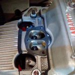
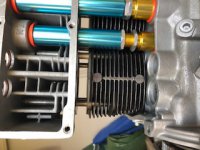
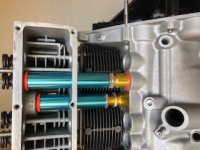
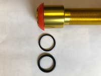
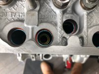
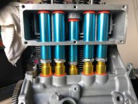
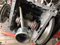
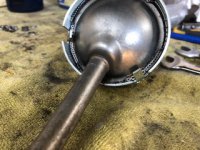
:eek::eek:

Hi Rob, Yes they can be made to perform well - it only takes a wad of cash :eek::eek:
Il Motori from Germany sell an 80bhp engine that revs to 8000rpm !!!! I think I would loose my sanity listening to it :eek::eek: and it costs €12000 + ouch!!!!
You should be able to find (somewhere) a Panda Head for around £300 to £350 ish
depending on any work done, if you go via a web supplier etc be prepared to double that (n)(n)(n)
Mod 500's post regarding the head studs is valid, but I am informed that given that dome nuts are fitted the turbulence is not too great unless you want hi flow hi output using bigger valves and a faster cam. Also a single port head can be prepared to give the same flow as a Panda head up to 6000rpm and then the panda head flows more and if prepared well will flow even more. It really does depend on what you want in the end. (y)(y)(y)
Ian.
 

Attachments

  • Unknown copy.jpeg
    Unknown copy.jpeg
    14.4 KB · Views: 849
Greetings - update. Got the flywheel (4.56kg) back on after making sure all the balancing marks line up and then fitted everything onto the engine stand. I'm informed that the crankshaft end-float is now 0.33mm. My engineer considered the upper figure of 0.44mm to be excessive (n)(n)
I proposed to make a start getting the VW adjustable pushrod tubes fitted and that's where I hit the latest snag :mad::mad::mad: The overall length is 130mm, but as the pic's show with the rather chunky seals fitted they are far too long and need about 20mm removed from the longer one's and 10mm removed from the small one to allow the head to seat properly. More later.
Ian.
 

Attachments

  • IMG_0229.jpg
    IMG_0229.jpg
    74.8 KB · Views: 42
  • IMG_0228.jpg
    IMG_0228.jpg
    35 KB · Views: 43
  • IMG_0227.jpg
    IMG_0227.jpg
    33.6 KB · Views: 69
  • IMG_0226.jpg
    IMG_0226.jpg
    29.4 KB · Views: 32
Mod 500's post regarding the head studs is valid, but I am informed that given that dome nuts are fitted the turbulence is not too great unless you want hi flow hi output using bigger valves and a faster cam. QUOTE]


I should have elaborated on my comment. I think the head stud issue on the Panda 30 head is one of the reasons why the aftermarket ones have the inlet ports further apart. It would be an easy problem to overcome if you are designing a new one.


I have seen those push rod tubes for beetles. I like that they are threaded to adjust rather than sprung. Are they good quality? I was hoping to get a set for my build.

Hi Mod, Yes I agree the problem with the studs can be overcome, but I am concerned that the otherwise short studs must be even shorter to fit under the modified manifold and they don't look easy to get at either (n)(n) The tubes came from 'Megabug' the lads there are most accommodating. I can confirm that they are good quality, it's a shame that they need shortening to fit the Fiat engine. Make sure that you get a set of the large orange seals too as they are very robust and are a very good fit into the crankcase with a slight fiddle on the head end. I will be using a larger o ring on the threaded end as an oil seal, the supplied one is a little thin!!!!
Ian.
 

Attachments

  • IMG_0232.jpg
    IMG_0232.jpg
    19.9 KB · Views: 21
The tubes came from 'Megabug' the lads there are most accommodating. I can confirm that they are good quality, it's a shame that they need shortening to fit the Fiat engine.
Ian.


I can confirm the MegaBug lads are a good crew, I have bought loads from them in the past (and no doubt will buy more)


Have I not seen these on Fiat sites though for the 500? why buy VW ones if there are fiat ones out there? (it may have just been in one of many weird dreams though):D


Rob
 
I can confirm the MegaBug lads are a good crew, I have bought loads from them in the past (and no doubt will buy more)
Have I not seen these on Fiat sites though for the 500? why buy VW ones if there are fiat ones out there? (it may have just been in one of many weird dreams though):D
Rob

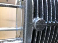
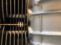
Morning Rob, One of the rather irritating problems with the 500/126 engine is leaky pushrod tubes (n)(n) The only proper replacement Panda head tube (the lower portion) is very expensive and like most others available rely on a spring to maintain good seal contact at each end. With a simple set of mods the VW tubes will fit, but the main advantage is that they can be manually adjusted up tight and if they leak can be removed if necessary without taking the head off and new seals fitted if required. (y)(y)(y)
Ian.
 
The best of the push-rod tubes for a 500/126 engine with a 'normal'head are the spring loaded tubes. These are expensive, compared to the 'normal' push-rod tubes, but they have the great advantage that they can be fitted/removed with the head still in situ (but the push-rods removed). I have a set on my '650' engine and with the thicker of the seals, have not leaked a drop.
 
Greetings - update, After getting the pushrod tubes all adjusted (cut) and the rocker rail supports (drilled) too I got some more time on the assembly. One problem with these VW tubes is that the Panda head casting webs get in the way of the adjusting nuts if you want to fit the adjuster on the upper end, so it's much easier and simpler to turn them the other way around. There is still not a lot of room to make the individual tube adjustment to fit, on the three inner tubes with the centre tube being the worst. You can get the finger tight, but the centre tube needed a drift and a hammer to rotate the nut (n)(n)(n)
I did find that when using the supplied orange seals the top of some of the tubes can line up slightly off-centre, this is again caused by the casting webs in the head. The solution I found was to torque down the head to 30nm and tighten the tubes nuts holding the tubes central in the head holes. Then after allowing the tube seals to settle complete the final torque down to 40nm and tweak the seals before tightening the lock nut. (y)(y)
The rocker rail mod was different in that I had to clean the complete assembly after stripping it apart. I'm very glad I did as the volume of dirt and grit from the oil gallery was alarming :eek::eek: 
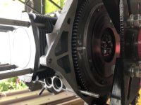
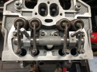
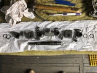
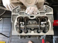
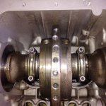
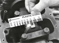
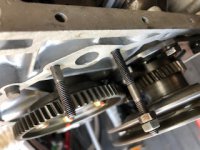
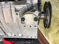
It all went back together easily and the new mounts have the added security of grub screws in the top to locate everything. More later.
Ian.
 

Attachments

  • IMG_0236.jpg
    IMG_0236.jpg
    32.6 KB · Views: 55
  • IMG_0241.jpg
    IMG_0241.jpg
    37.3 KB · Views: 42
  • IMG_0240.jpg
    IMG_0240.jpg
    40 KB · Views: 43
  • IMG_0239.jpg
    IMG_0239.jpg
    31.2 KB · Views: 70
  • IMG_0238.jpg
    IMG_0238.jpg
    34.7 KB · Views: 85
Greetings, quick update on progress as I'm not getting as much time as I would wish on the job (n)(n)
I set about the assembly of the rocker rail and the adjusting of the tappets today and promptly hit a slight snag. Although the reassembly of the rail with the steel mounts was completed correctly I found that the number two rocker was binding tightly on the rail as it moved around the rail itself :eek::eek: The problem was that the outside shoulder of the rocker arm was too tight against the steel support, the other arms did not have this problem. :mad::mad: The solution was to simply slacken off the mount nuts and the grub screws and then gently tap the end of the shaft with a light hammer to move it along the head within the mounts. The movement required was only a 1 or 2mm at the most, but it was enough to give all of the arms room to move correctly. (y)(y) More later.
Ian.
 

Attachments

  • IMG_0244.jpg
    IMG_0244.jpg
    37 KB · Views: 46
Greetings, Getting a bit more time on the build I swung the engine upside down on the engine stand to get at the sump for access to fit the oil pick up. But when I rotated the crankshaft I noticed that there was appreciable movement of the big end about the crankshaft journal without any corresponding movement of the crank itself. !!:eek::eek::eek: Funny I thought, not noticed that before (n)(n)
So after a quick chat to my engineer I took said engine back to him for diagnosis. At this time I was having all sorts of thoughts about the cause (all bad) wrong bearing shells, wrong crank grinding etc etc. I was thinking that the whole thing would have to come apart again :mad::mad::mad: Anyway Alistair my main man, kindly set about stripping both of the big ends and measuring everything. The result was that the reground journals are correct, the shells are correct and after using a very small piece of plastic clamped in-between the journal and the shell he told me that the clearance was 2 thou and given that the limits are from 1.5 to 3.0 thou everything was in order - the relief was palpable !!!!!:D:D So I hear you ask what was the movement I felt ??
Well after a bit of engineer speak Alistair announced that it was caused by the backlash in the new timing gear set, which would otherwise not have been evident had there been a chain timing gear used with a self tensioning chain to take up any backlash !!! You learn something every day (y)(y) More later.
Ian.
 

Attachments

  • IMG_20190226_110612.jpg
    IMG_20190226_110612.jpg
    2 MB · Views: 26
  • s-l225.jpg
    s-l225.jpg
    9.5 KB · Views: 926
Would that not be the tolerance allowed for the flow of oil around the bearing during driving conditions?


I once was trial fitting parts together before a true assembly using engine building paste/grease and thought a set of big end were wrong but after a few measurements it transpired everything was ok. I then trial fitted them together again with a good slurping of engine oil and it was like they were different parts...…..
 
The running clearance would most likely have been imperceptible to touch. The unnerving delayed movement you felt sound similar to what happened with my 900 van engine. I thought the crankshaft pulley keyway was worn or the key damaged as I could rotate it about 10mm without moving a piston. But it was the same thing....in my case a ridiculously worn timing chain.
 
Ian, how do you use that Plastigage on a main bearing; these slide over to fit rather than being clamped.

Hi Peter, Not sure that you can (n)(n) I would think that because all main bearing journals are routinely reground to a specific limit once they are deemed out of round or worn, the testing of the journal bearing for fit would be unessessary. Unless you measure the bearing face for wear and round separately I cannot see how a 'plastigage' would work effectively ???
Ian.
 
Would that not be the tolerance allowed for the flow of oil around the bearing during driving conditions?
I once was trial fitting parts together before a true assembly using engine building paste/grease and thought a set of big end were wrong but after a few measurements it transpired everything was ok. I then trial fitted them together again with a good slurping of engine oil and it was like they were different parts...…..

You are correct Rob, according to my engine man it's only when any wear in an engine becomes significant that you start to hear it, the slack in the system is normally taken up by oil :eek::eek:
Ian.
 
OK time for a few small jobs today, the oil pick up and the extension to it needed fitting, but the studs had to be put in first. so after cleaning everything well I assembled the pick up and extension and noted that the cut out in the side was not big enough for the pick up tube (n)(n) 
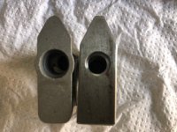
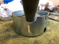
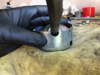
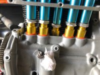
So the file came out and an adjustment was made sufficient to get a good fit. (y)(y) The extension is made to sit against the bottom of the sump under the tension of a spring and the only parts to hold it together are three small tabs that must be bent over, a bit of a faff but effective.
I had to fit a blanking plate over the fuel pump mount as I am using the same electric fuel pump on the car. (y)(y) (y) I finished off with a quick final tweak of the pushrod tubes and locked them up. I have to get some tinware parts powder coated soon too. More later.
Ian.
 

Attachments

  • IMG_0255.JPG
    IMG_0255.JPG
    66.4 KB · Views: 37
  • IMG_0254.jpg
    IMG_0254.jpg
    38.8 KB · Views: 31
  • IMG_0252.jpg
    IMG_0252.jpg
    28.1 KB · Views: 48
  • IMG_0248.JPG
    IMG_0248.JPG
    61.6 KB · Views: 35
  • IMG_0247.jpg
    IMG_0247.jpg
    33.2 KB · Views: 34
  • IMG_0257.jpg
    IMG_0257.jpg
    60.2 KB · Views: 59
  • IMG_0258.jpg
    IMG_0258.jpg
    34.1 KB · Views: 33
Hi, Ian,

If that extension actually contacts the sump when the sump is in place, I think I'd like to see more holes for the oil to be drawn in - I can only see 1 hole in the pics. Maybe run this by your Engine Man for his assessment?

Normally, afaik, there is usually at least a 6-8mm space between the oil pump pick-up screen and the sump, so this area (6-8 x circumference of oil pick-up screen mm2) would need to be matched by the total area of any holes in the extension.

I've even run engines without the pick-up screen in place to minimise any restriction at the oil intake to the pump - I wonder how much power it takes to suck oil through such small holes, plus it possibly also adds unwanted heat into the oil. But this was on engines that had an anti-drainback valve in the oil filter, idk if it would be safe on the 500?

Also, if there is any possibility that fitting the sump will try to push the extension up against the spring pressure, you might need to extend the notched cut-out a bit more.

Great workmanship and attention to detail, so far. (y)

Regards,

Al.
 
Back
Top