Hi Ian,
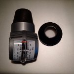
I don't know why you invested in a carb. syhchroniser, don'tcha know that all classic car mechanics traditionally used a length of tubing held up to their ear...
although it might be possible/safer to use modern electronic equipment to instead measure the frequency? of the sound of the air being drawn into the carb.
Too late for me, I'm going deaf....
")
I would have suggested a different type of carb synchroniser - went looking online for an illustration/supplier and found
www.holder.co.uk
(see carb. synchroniser part no. 090.043 @ £26.92 + vat),
unfortunately they out of stock at present. The advantage of this type is that it incorporates a baffle allowing you to get the float in the middle of the scale which makes for more accurate interpretation of the reading and the float tube can be swivelled to set it vertically regardless of carb intake angle.
This website ^^^ is imho well worth a look as they have lots of tools and bits/pieces relevant to those who work on a classic car. This Co. is also a Morgan Dealer for the Midlands? (so likely good people!).
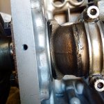
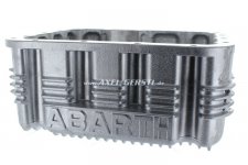
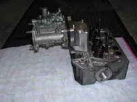
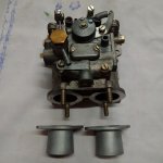
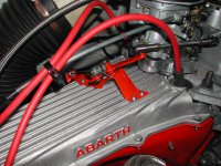
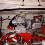
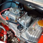
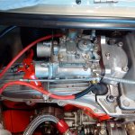
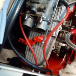
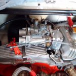
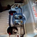
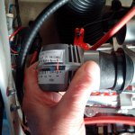
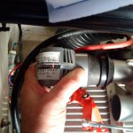
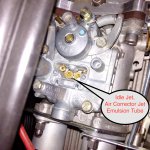
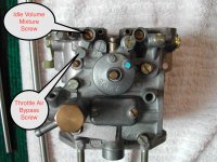
I'm wondering about the slight difference in the readings on your synchroniser? Aren't the two throttle plates attached to the one fixed throttle shaft i.e. no adjustment? If so, the difference in readings is possibly down to slightly different idle mixture settings? Iirc this carb has separate idle mixture volume? adjusting screws for each choke?
(I've no manual to hand to check)
Maybe the use of 2 x Colourtune devices (transparent 'spark plug' to allow sight of flame colour which is a visual indication of mixture strength) might be useful or alternatively use of an exhaust gas analyser although iirc you're just doing some initial work before bringing the car to a rolling road?
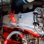
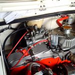
Anyway, you're making great progress
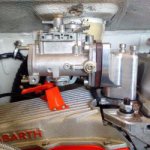
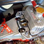
Well done on the neatness of your bracketry and problem solving as you go along. Very impressive
AL.