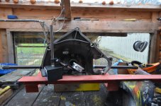
I've taken on some experienced advice from Bleeding Knuckles and Toshi 975, combined it with the information readily available via YouTube etc. and made a start.
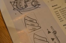
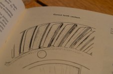
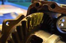
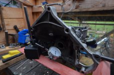
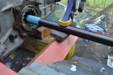
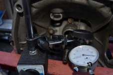
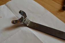
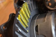
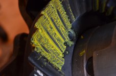
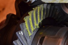
I haven't yet got a stand and extension tubes for my dial-gauge so all I've done so far is to assess if the pinion depth into the crown-wheel is about right. I'm told that it should be, if assembled properly before I dismantled it, as the new gearbox bearings probably don't change the settings. It wasn't right at first so I took out a shim, played with the backlash, checking it by feel and adjusting with my homemade tool. Eventually, as seen in the last image, I think I got there with a contact pattern as shown in one of my manuals. There are conflicting images of the ideal contact pattern in some websites but I'm happy with this for now.
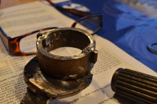
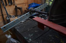
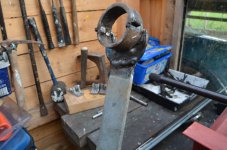
So next thing I need to properly re-assemble the differential and bell-housing and then to check the backlash using a gauge, set the bearing preload on my home-made support frame and the final crown-wheel contact pattern, which I hope I can see through the input shaft hole.
I haven't yet got a stand and extension tubes for my dial-gauge so all I've done so far is to assess if the pinion depth into the crown-wheel is about right. I'm told that it should be, if assembled properly before I dismantled it, as the new gearbox bearings probably don't change the settings. It wasn't right at first so I took out a shim, played with the backlash, checking it by feel and adjusting with my homemade tool. Eventually, as seen in the last image, I think I got there with a contact pattern as shown in one of my manuals. There are conflicting images of the ideal contact pattern in some websites but I'm happy with this for now.
So next thing I need to properly re-assemble the differential and bell-housing and then to check the backlash using a gauge, set the bearing preload on my home-made support frame and the final crown-wheel contact pattern, which I hope I can see through the input shaft hole.
")