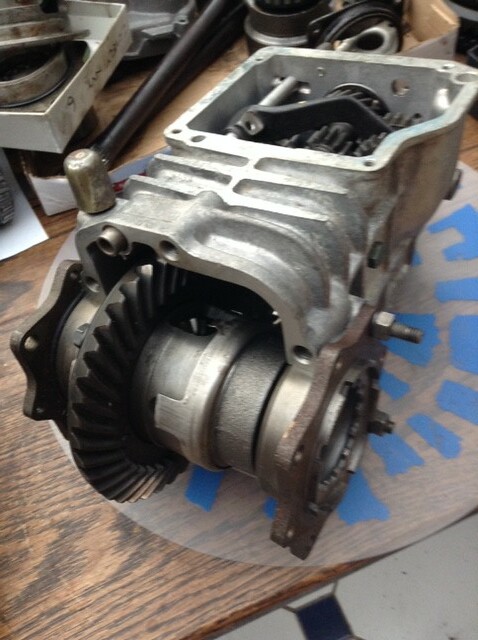
Technical Gearbox Rebuild 2nd Gear Synchro Unit

Currently reading:
Technical Gearbox Rebuild 2nd Gear Synchro Unit

I have kept the original diff set up for the gearbox. That way as long as you can mate the bell housing properly you wont have a problem with the diff set up.
However if you use the diff from the box with the bell housing, then you will need to rest the diff. That then gets tricky:cry:
Which part is wider? the box or the bell housing?
 
I have kept the original diff set up for the gearbox. That way as long as you can mate the bell housing properly you wont have a problem with the diff set up.
However if you use the diff from the box with the bell housing, then you will need to rest the diff. That then gets tricky:cry::confused::confused:
Which part is wider? the box or the bell housing?

Hi Sean, I’ve had a think about the pinion and crown wheel issue and wonder is it is advisable to fit the pinion from the BIS box to the 126 crownwheel:confused: or must I fit them as a pair??? I don’t want to bugger the box as that would really p**s me off :mad: If I change the crownwheel will I still need to reset t(n) the adjustment - I think I’ll find my dial gauge anyway just in case of too much backlash: : (n) The Bellhousing is the wider part, Ill have a think about the machining of the bearing retainer area, but, I do consider that it would have to be last option if all else fails - fingers crossed it all goes back together ( is it too much to ask for no leaks :p ) without a hitch - maybe ,!!!!!

Ian.
 
is it is advisable to fit the pinion from the BIS box to the 126 crownwheel:confused: or must I fit them as a pair???

Apart from the possible differences in the tooth geometry and number of the two types of crownwheels and pinions, each setup is a matched pair from the factory. According to the information I have, there will be inscribed data on them to show this pairing and to give the instruction as to the thickness of shims the pinion will need to centre it with the crownwheel. This would be reall trial and error with mis-matched pairs.
This is an area of 500 mechanics which intrigues me and I would love to know more about it from someone who has done it using minimal technological aids.
Reason being. both the hgearboxes I have used have worked really well but both have a distictive whine from the diff which I would love to get rid of by using new bearings and proper adjustments from first principles.
 
Hi Peter, thanks for the info, I guess I shall have to fit the pair then. I know what or who will be whining if I don’t get this right ME!!! :mad::mad::mad:
I understand what you say about the adjustment of the crownwheel backlash and the driveshaft turning torque, but without the tool to mount the dial gauge and adjust the bearing retainers, it will be difficult to achieve an accurate figure. I gather from a mechanic mate that the turning torque can be achieved with a simple spring balance and some string!! (y)

Ian.
 
Peter jumped in there before me - some of us have jobs you know!


Totally agree, best to keep a matched set of crown & pinion.
That's one of the reasons I have kept my diff for the 126 box. The pinion is on the main shaft and this has a number of shims behind it that sets the pinion onto the crown wheel. Too little and you will have a gap and cause wear and also play between the two - causing probably damage within a short time. Too many shims and this will cause it to tighten up and also cause wear. I'm not sure which is causing a whining noise - I thought this was in 1st gear only - well it is on mine.
Due to the position of the crown/pinion its tricky to set up.
I suppose you will need to fit the pinion in place with all the lower gears and bearings. Then fit the diff and the bell housing - oops there's your next problem. Once that is tightened with the gaskets in place you can then check if there is any backwards/forwards movement on the pinion shaft. Ideally you want to start off with a small amount of play and then you will need to measure this, then remove everything and fit the required shims behind the pinion head.
Not easy, wont be quick but it should be possible.
 
:D:D:D
How on earth could I go out today with a hurricane forecast? Even I'm not so cruel as to subject poor little Murf to all this weather.:D:D:D

Did you get the “end of the world gloom” all the way up there?

I was working outside today in just a T shirt, the next thing I know someone switched the lights out and I had to get my coat from the van. I could barely see what I was doing, even with my glasses on!!!!
 
Did you get the “end of the world gloom” all the way up there?

I was working outside today in just a T shirt, the next thing I know someone switched the lights out and I had to get my coat from the van. I could barely see what I was doing, even with my glasses on!!!!

"End of the World!"....just what we said. At 2.30pm it was really dark.... as in lights definitely needed on the car and in the house.....not just advisory. Horrible day. All my work (as in work-work) :D was indoors today and conducted by phone and via internet. But it will free up some time for fillering and painting later in the week.:) ....and back slightly on topic, I am going to try this diff. rebuild thing on the gearbox off my 594 engine which looks like it's been attacked before so nothing to lose.:rolleyes:
 
"End of the World!"....just what we said. At 2.30pm it was really dark.... as in lights definitely needed on the car and in the house.....not just advisory. Horrible day. All my work (as in work-work) :D was indoors today and conducted by phone and via internet. But it will free up some time for fillering and painting later in the week.:) ....and back slightly on topic, I am going to try this diff. rebuild thing on the gearbox off my 594 engine which looks like it's been attacked before so nothing to lose.:rolleyes:

Over here in Ireland the storm was bracing and a lot of bins went walkabout, but we were lucky compared to some others. Go for it Peter, at least we can compare notes !!!! Before I reassemble things I shall make sure that the pinion and crownwheel are a set a keep my fingers crossed(y)

Ian.
 
I think someone may be ready to step in and help us, starting with this.........

AF867858-3167-4673-B269-7FC3FA92471F by Peter Thompson, on Flickr

Thumbs up to Peter for posting my picture as I could not make it work. Think I am more Meccano than techno :)
The idea of rebuilding a gearbox frightened the life out of me until I realised that I had accumulated seven 126 gearboxes that were broken or of unknown condition. So something had to be done and I stripped all of them down to the last nut and bolt. Following a Haynes manual is fine . Cleaned everything up and found a range of diverse problems apart from the usual 1st/reverse wear & damage. After sending the obvious scrap to the recyc bin I laid everything out on the table. Following the manual makes the gearbox assembly quite easy so I assembled one with all new parts then two more with some new parts where required. Because I mixed and matched parts apart from the crown wheel and pinion sets I had to set the backlash on the diffs. I did retain the shins on each main shaft as that seemed a good starting point then had a think about the diff set up. So it seemed to me that the shims on the main shaft were there to get the best alignment of the pinion helical tooth working surface on the crown wheel so started there. Then the backlash adjustment can be set by the adjusters on the drive shaft/diff bearings. How to do this was the big question?
Without factory tools that is. In the picture the main gearbox internals are assembled , the main shaft nut nipped up and the big drive shaft/diff bearings backed off on the adjusters. With the bearing retaining studs removed from the bell housing I fitted the bell housing in place to make sure the bearing housings were pressed well home then locked the bearing housings in place on the two studs each side on the gearbox casing. Then remove the bell housing by tapping it out forwards. Can only do a visual inspection of the meshing between the crown wheel & pinion. Adjust the bearings to get contact on the diff. If the alignment looks good then proceed otherwise the main shaft shims will need adjusting so you have to go back to square one. Going forward you can then adjust the bearings to and fro to get a good running taper roller bearing assembly whilst at the same time checking the backlash with a dti. Off the top of my head I think the backlash should be 0.001 to 0.004". I have also checked the backlash by leaving out the gearbox input shaft and working through the hole in the bell housing. Bit fiddley but it works.
 
Last edited:
Foot note to above. When I said that I mixed and matched the crown wheel & pinions I meant with different gearbox casings. I always kept the matched diff parts as a pair. I also remembered this morning that when I set the backlash with the bell housing in place and the gearbox input shaft removed I also removed the input shaft bearing housing which gives you a little more room to play with. As a push rod through the hole onto the crown wheel I used a small length of thin dowel and some blutack checking the travel with the dti.
 
Well, I managed to sort the Tripod CV kit problem (as in where to purchase) (y) The latest prices I can find are Ricambi is £227.88 Proietti is 119.95 + vat each shipping extra for both.:eek::eek::eek: So I just got hold of Toshi in time before he departs to the south (thanks Dave) for the princely sum of £190 all in (y)(y)(y) It still seems that Motormax still don't list them as available and they don't answer emails either :mad::mad: Now, all I need is my engine back from the engineer chap :worship:

Ian .
 
Last edited:
Question for the Great and the Good on here :worship::worship: the instructions for the Motormax Tripod CV kit dictate that the Hub Nut be fitted Nylon side first (see pic) :confused::confused: Can anyone who has fitted this kit tell me if there is a problem with lining up the (metal) threads of the nut with those of the stub axle once you have screwed the nyloc nut on the wrong way as it seems to be a bit hit and miss (n)(n) thanks

Ian.
 

Attachments

  • stub nut .doc
    204.5 KB · Views: 47
I have fitted these and have used the MOTOMAX instructions.
I have no recollection of this issue but will re- read instructions and get back to you.
 
Can anyone who has fitted this kit tell me if there is a problem with lining up the (metal) threads of the nut with those of the stub axle once you have screwed the nyloc nut on the wrong way as it seems to be a bit hit and miss .

Ian, could you not screw it the right way and cut a thread in the nylon insert and then flip it round.?
n
 
Ian, could you not screw it the right way and cut a thread in the nylon insert and then flip it round.?
n

Hi Peter, Yes my thoughts too, but I have always understood that a 'nyloc' nut should be used once only, otherwise the locking action or the grip of the nyloc is degraded and I would hate to have everything 'loosen up' in the hub area during operation :eek::eek::eek: maybe some strong Loctite will solve the problem??

Ian.
 
Hi Ian,

I've never heard of instructions to fit a Nyloc nut 'the wrong way around'....

I've been wondering why this instruction?

Maybe there wouldn't be enough thread protruding through the nut to allow the nylon ring to grip. In which case get a longer shaft:rolleyes: or a shorter nut.:)

Maybe the seating for the nut in the CV body is not flat?

If it isn't, I'd suggest looking in the possibility of having it spot-faced flat and fit the nyloc nut the correct way around. (I accept you might not have the facilities to do so and might be loathe to pay to have this done, given how much this conversion has already cost you :eek:)

Re: finding the starting position for the nut if fitting it 'the wrong way around'?

You could measure the thread pitch and compare this with the thickness of the nylon ring in the nut to determine the starting position of the nut on the threaded shaft. e.g. if the pitch was 1.25mm and the nylon ring was 2.5mm thick then that equals exactly 2 turns on the nut , so aligning the start point on the nut with the start point of the shaft thread would work fine. However it's unlikely the calculations will work out so conveniently.

If you just happened to have a taper tap of the requisite size 16mm?, 18mm? laying around, you could run this through the nyloc nut to lightly mark the starting position. Don't have such a tap lying around? Nor do I! :D

You could use a thread gauge to 'follow' the thread around from the end of nut to locate the starting point on the nylon ring.

Re: running the nut on in the correct way to locate the starting point on the nylon ring? I agree this is not 'technically' correct but we've all probably done it at some time or other ( on cars but afaik never on aircraft etc). I seem to remember a sort of 'rule-of thumb' in deciding if a nyloc type nut could be re-used. Basically if you could turn the previously used nut with your fingers, then it was useless as a self-locking nut. At a pinch, I've 'adjusted' the top of the nut downwards a little to compress the nylon ring to regain some grip on the thread allowing re-use.

I've got to ask! Are these tripod joint kits available in any other colour....:D

AL.
 
I have one of the "Motomax" C/V kits sitting in my workshop (to go on my car when I fit the '5 speed' gear-box', so I dug it out and inspected it. The rounded end of the nut (the nyloc end) fits snugly into the inside of the part of the joint that fits onto the stub-axle shaft. If the nut was fitted the 'correct' way round there would be very little of the nut in contact with the coupling--only the corners of the 'hex' in fact.
There are 2 ways round this problem--both involve a machine shop (or the clever use of a lathe)--(1) have the nut/coupling contact area machined flat or, (2) have a special little washer made that will fit snugly into the coupling and also allow you to fit the nut the correct way round. (y):)
 
It all sounds like a bit of a design compromise with that reversed nut.
If I was fitting it there would definitely be a dab of Loctite on the threads.

If you precut the threads into the nylon by screwing on the normal way first, I don't think you compromise the strength of the locking. The nylon will not become deformed in the way that it does when tightened properly because it will not be loaded with torque.
 
Back
Top