General Introduction and my new 1969 500L

Currently reading:
General Introduction and my new 1969 500L

I realise it might be a pain in the bum Katie, but may I suggest that you move your 'T' piece closer to the metal fuel pipe (even maybe trim the length of the metal pipe) so that the 'T' piece is not sitting over your alternator. If there ever was a leak from any of the connections on your 'T' piece, it would drip straight on to your alternator. I have mounted my 'T'piece on the side of the engine bay (with rubber-lined 'P' clips)---well clear of anything hot or electrical. Other than that, 1st class job, well done the pair ofyou.
 
I realise it might be a pain in the bum Katie, but may I suggest that you move your 'T' piece closer to the metal fuel pipe (even maybe trim the length of the metal pipe) so that the 'T' piece is not sitting over your alternator. If there ever was a leak from any of the connections on your 'T' piece, it would drip straight on to your alternator. I have mounted my 'T'piece on the side of the engine bay (with rubber-lined 'P' clips)---well clear of anything hot or electrical. Other than that, 1st class job, well done the pair ofyou.

Thanks Tom. We plan to keep it where it is for now and check it regularly. The connections are positioned to allow easy inspection :)
 
Hi all,

We reassembled the doors over the weekend (pics to come soon) and then came to hang them. The drivers door took some adjustment but we've managed to get the gaps good all the way round and the closure mechanism feels good and positive. It takes a little bit of slamming but I think that will ease when the seal wears in more. The seals are from the original car btw.
The passenger door however is a different story. The hinge end seems to sit too close to the front quarter panel and unless there is a large panel gap, will contact on opening. The other end of the door won't fit in the hole once the striker catch is installed. The catch on the B pillar contacts the door. It seems whichever way we adjust to get one side right, the other gets worse. We are doing this initially with no seal installed and no striker catch.

We have measured the door apertures and doors in several dimensions (horizontal, vertical and diagonal) to check that something didn't go wrong at the bodyshop and both sides are equal (within mm)

Does anyone have any suggestions on why we can't get it to align properly? Could it be the hinges? There was quite a bit of paint on the back of the hinges and so we have removed this to get some further adjustment but it doesn't seem to have helped :confused:
 
Are they the original doors and hinges Katie? For a number of reasons, I had to purchase,fit-out and fit 'pattern' doors, both sides. Like you, 1 fitted and was adjusted really easily---the other door was a bitch! It turned out that one of the hinges (which came with the doors) was totally mis-shapen,to the point that we had to cut it along its length, open it out slightly and weld it back together. Strangely, that door ended up the better fitting of the 2!
The only way we could see that it WAS the hinge at fault was by laying the 2 doors on their backs and checking the hinge alignment against each other. What should have been about a couple of hours work absorbed 2 evenings (we were working in the evenings, after work, at the body-shop my friend was senior estimator at).
 
Does anyone have any suggestions on why we can't get it to align properly? Could it be the hinges?

Looking at this laterally it my not be entirely a problem of the doors' making, I took a lot of care to fit the front wings using the original doors as guidance. But in my case I ended up with a gap on the drivers side between the door and trailing edge of the wing which was too wide. There is leeway in the way the flangeof the wing is pressed for the edge to be in variable positions. I ended up welding a narrow fillet to the wing to cover the gap.

In 1983 I had a Fiat 500 that had never been welded (it had a few tin cans fibre-glassed in) but the front door caught really badly on the edge of the wing. My C3 Picasso has been like at the bottom of the door since nearly new.

So I have no suggestions for a solution but plenty of empathy and consolation for a very stressful and irritating issue. You seem to have tried everything; can you possibly negotiate with the bodyshop for a cure?
 
Hi both,

Thanks for the replies.

As far as I know, the doors are original and they fit when they came off the car. I don’t remember them fitting perfectly but they were certainly in the door aperture with working locks.

Curiously, it’s the drivers front wing that has evidence of welding and that door fits well.

We will have another crack after work today and see where we get to. If we have no joy then the bodyshop are only 5 mins down the road.

Cheers.
 
Hi all,

We recently rebuilt the doors on our little fiat, and as I had the opportunity, and I couldn't find a comprehensive guide online, I thought it would be good to put together a comprehensive photographic guide on how to reassemble the doors on a Fiat 500 L. This guide might be a bit simplistic for those more familiar with the 500, but for any newbies I hope this is useful and helps them avoid the pain that we had to go through!


Step 1.

Collect all your parts and tools. I used a multicompartment box with labels to make sure I had all the bolts, washers etc. in one place with the minimum of faffing about. You’ll also need your door keys.

Tools required are:

Ratchet wrench + ratchet extension
8mm ratchet (for the door handle bolts/window regulator)
PH2 screwdriver or bit (for the door lock/latch, door guides, quarterlight fittings)
Pliers (for the plastic door lock connector)
Some beer mats (yes, really)
Plastic faced mallet
Hacksaw
Waterproof grease
Loctite 243 or similar
Tube of adhesive or sealant such as silicone + caulking gun
Biscuits


Step 2.

Make a mug of tea: this is essential to a successful door reassembly! Extra points if you have it in a car themed mug.

50308273288_bac473555b_b.jpg


Step 3.

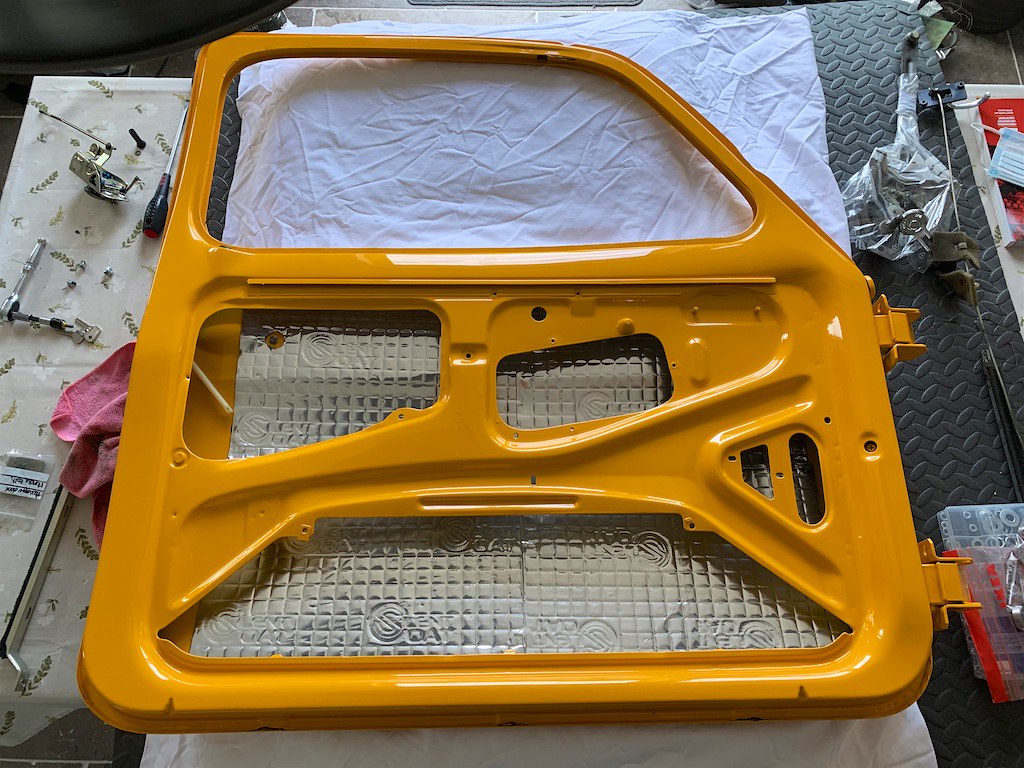
You’re going to need a large work area for the door. You have the option to fit them to the car, but I think it’s much easier on your back if you can put the door on a table. The doors are relatively heavy, and the door skin thin and fragile, so I used some foam tiles, old pillows and a blanket to help support the weight and protect the paint/door skin.

50309112887_4d90eb447c_b.jpg


Step 4.

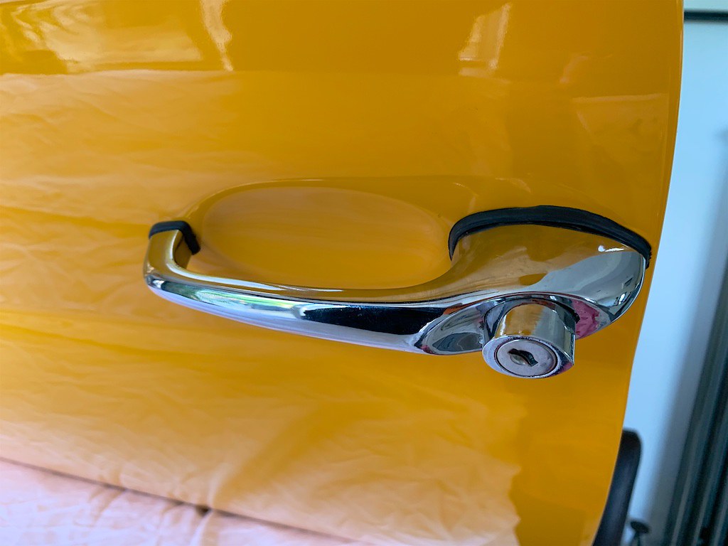
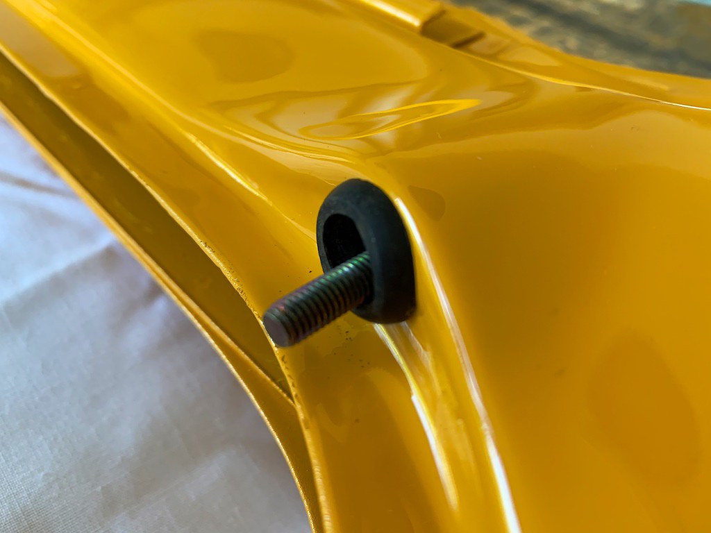
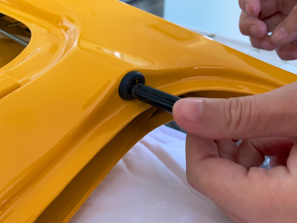
Fit the plastic rod (the one that connects the exterior handle to the latch, reason for this will be clear later) to the exterior door handle, and thread the mechanism through the hole in the door from the outside. Use an 8mm socket and some loctite on the bolts. Don’t forget the washers and the rubber pads that go on the back of the handle.

50308948376_31fdd6b0df_b.jpg


50309112957_77b489d5ca_b.jpg


Step 5.

Fit the rubber grommet that goes around the hole for the interior lock at the top of the door.


Step 6.

Offer up the latch mechanism by passing it through the door from the inside whilst also threading the interior door lock mechanism up through the hole at the top of the door. If the latch is locked use your keys to unlock it now.

50308272678_f7fd9f112a_b.jpg


50308272908_0061a3fc0b_b.jpg


Step 7.

Assuming your interior handle is already attached to the relay rod, thread the interior door handle into the door by passing it through the hole in the door from the inside, and threading the relay rod across the door towards the latch. Pass the kinked end of the rod through the receiver on the door latch. This is MUCH easier to do when the latch is unattached and floating in space. Clip the relay rod into the 2 holes on the door, don’t forget the little foam anti-rattle pads.

50308948436_0560f17ca0_b.jpg


50309113037_baf9848f35_b.jpg


50308948486_3979c474b1_b.jpg


50309113097_6998a573fa_b.jpg


50308272803_4673726e86_b.jpg


50308272853_87773ca21c_b.jpg


50308948681_7575212e95_b.jpg


Step 8.

Use 3 conical screws and serrated washers with loctite to secure the door latch mechanism.

50309113377_19c1cc376c_b.jpg


Step 9.

Fit the plastic rod to the door latch with pliers. It's easier this way around because there is better access to this end of the rod.

50308272938_323af68821_b.jpg


Step 10.

Fit the plastic golf-tee to the interior door lock.

50308272973_fba449e42e_b.jpg


Step 11.

Fix the interior handle. The plastic plate goes behind the metal part of the door. The threads are only in plastic, so be careful how tight you go. If they are threaded (one of mine was) you can use a longer bolt with a washer and a nut on the back.

50308272998_fc6803a04b_b.jpg


50308273038_c29a019e10_b.jpg


Step 12.

Test the lock mechanism for correct function. Stand back and scoff at how easy that was. Realise the hard bit is yet to come. Drink tea and stare into the middle distance whilst questioning your life decisions.


Step 13.

Make more tea, get biscuits: This is the tricky part.


Step 14.

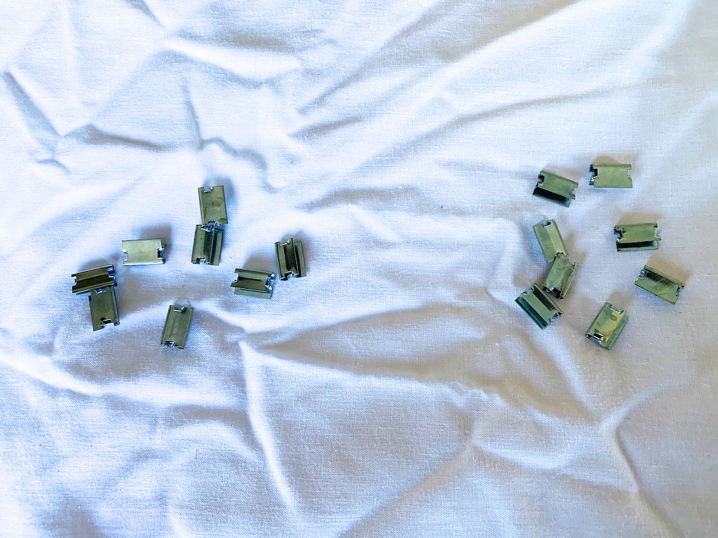
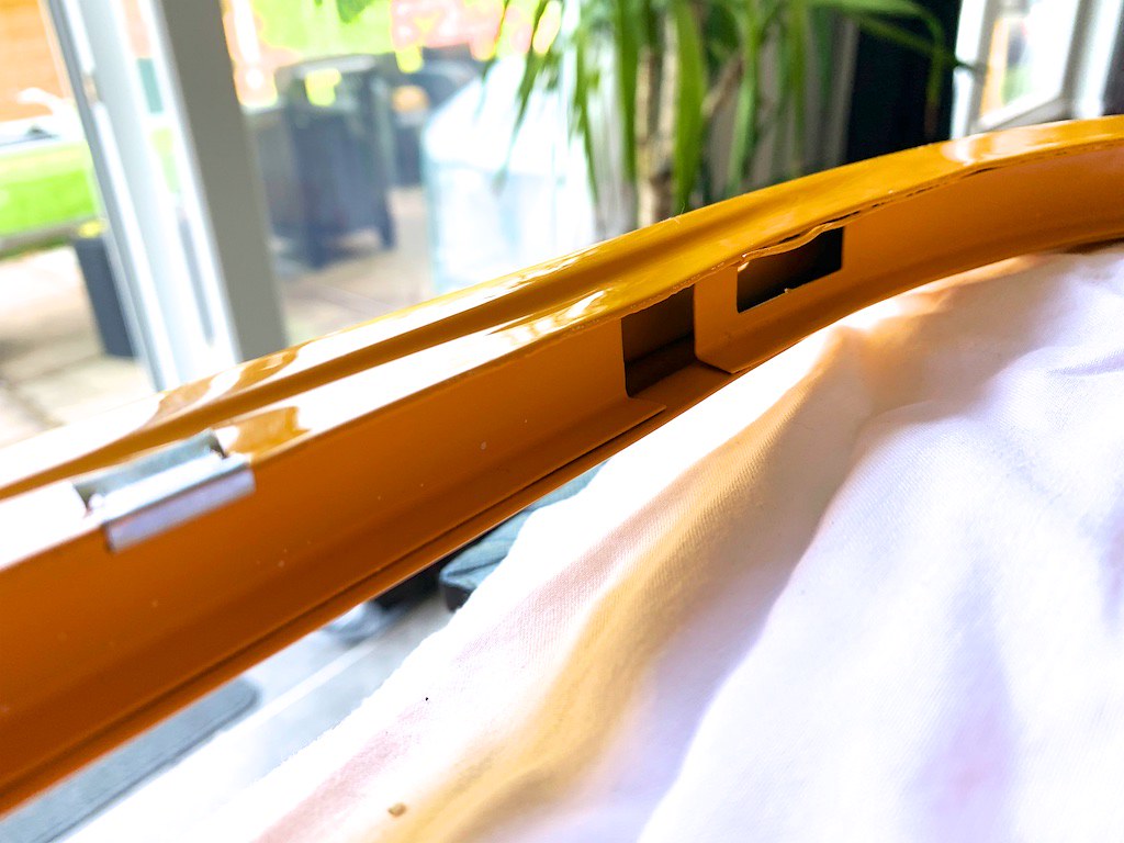
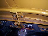
Fit the window surrounds and trim clips. I show here the approximate location of the clips that worked for me, I used 6 per side.

50308948706_9dbe83fd18_b.jpg


50308948861_d7f6ebca80_b.jpg


The important bit is not to put the clips right where the reinforced (double skinned) parts are for the quarterlight.

50309113397_289074b1d9_b.jpg


I used a small plastic faced hammer to tap the clips on, this seemed to avoid damaging the paint. You can also see the clips are asymmetric, the longer tail of the clip goes inside the door.

50309113382_913e67ca43_b.jpg


50308273148_d9a6316dd5_b.jpg


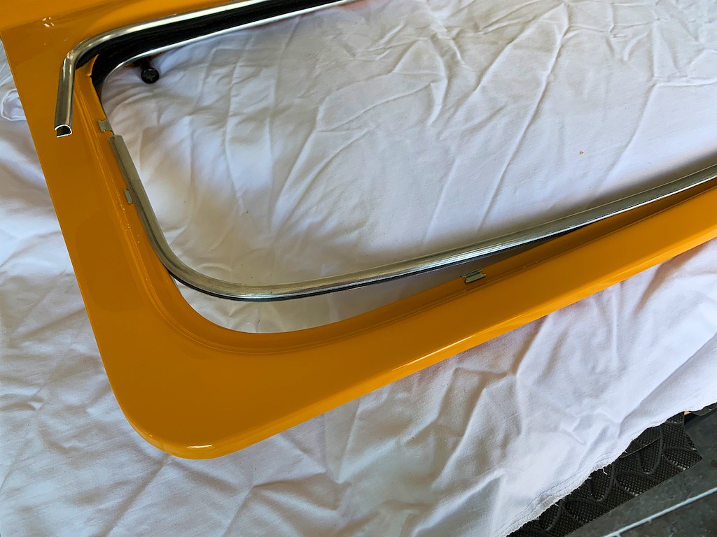
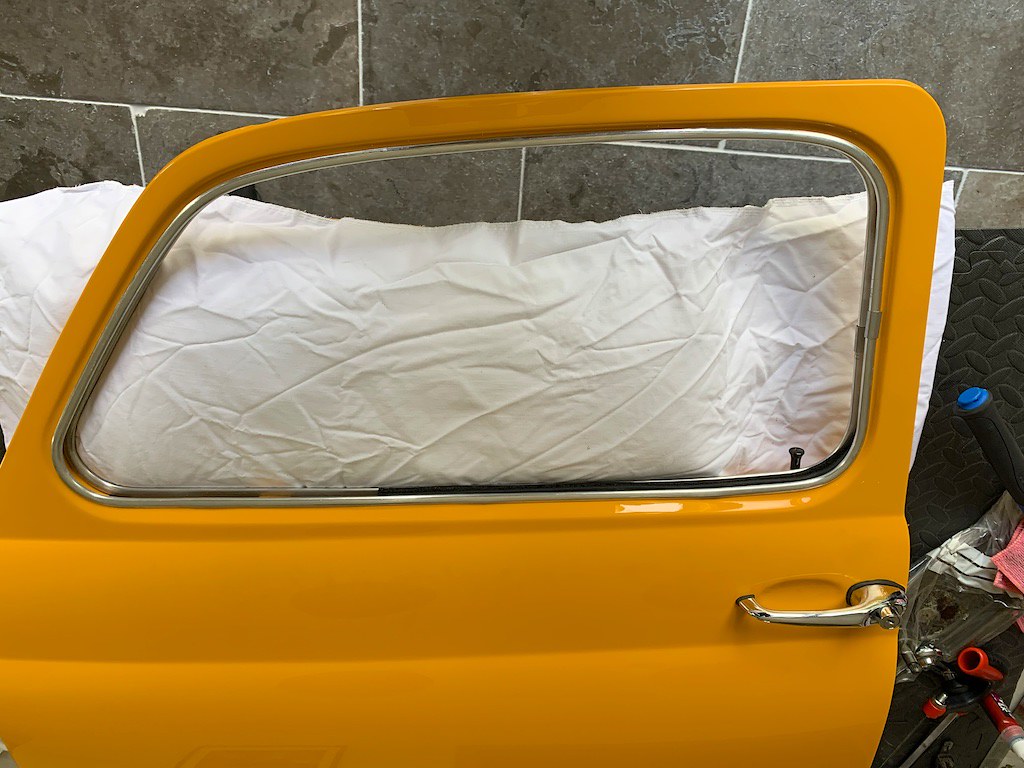
I started the trims in the front corner of the window. Once the trim is on it won't be coming off without being damaged, so luckily it’s easy to fit and snaps into place.

50309113507_7ef1797d4f_b.jpg


50308948901_cf36f870d1_b.jpg


Continue around the window and pull them into place, being careful not to kink the trim at you go

50309113532_89c06036bd_b.jpg


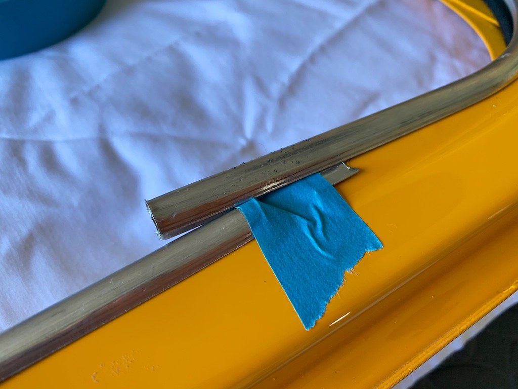
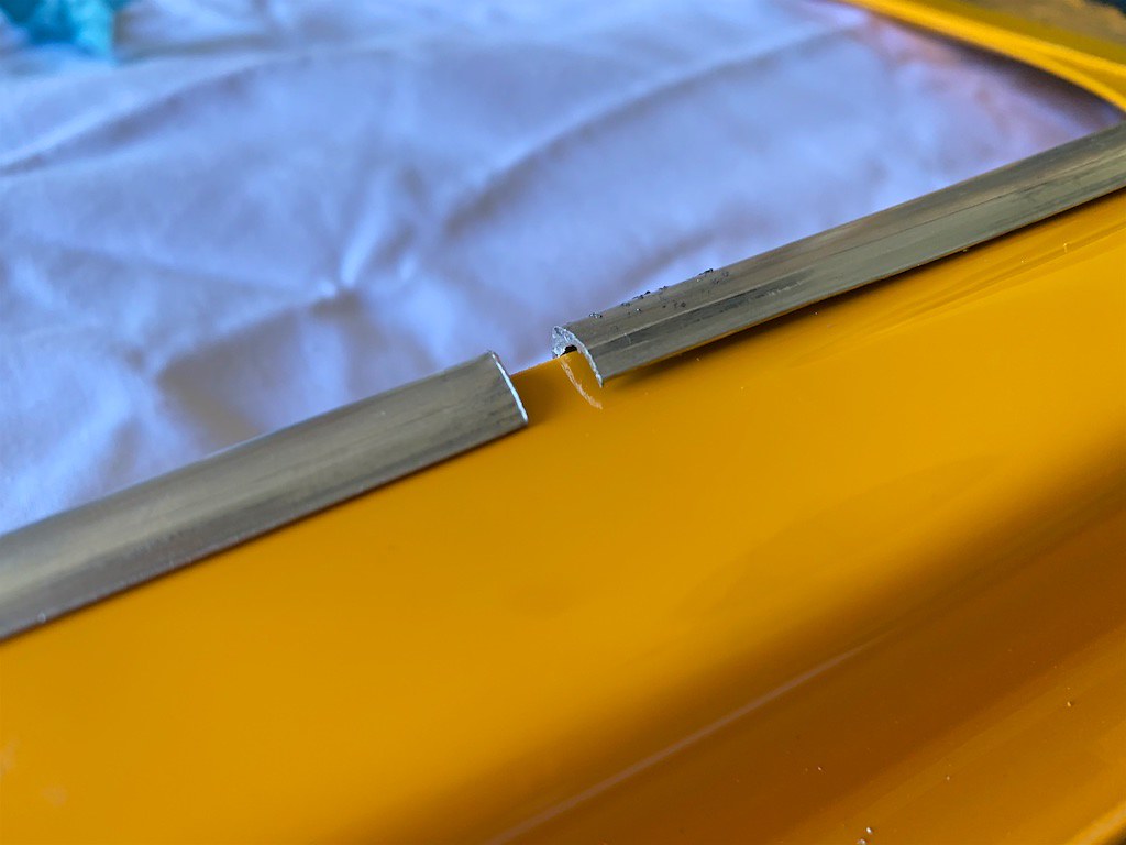
The trims need...trimming to fit properly. I used some tape to protect the overlapping trim and a hacksaw to trim it without distortion.

50308273163_817a41a0c7_b.jpg


50308948846_08d3995643_b.jpg


50309113442_f1628d6f6c_b.jpg


Note: The trim sections that cover the join are also asymmetrical and need to have the flat side facing the inner door.

50308273183_2e0a055516_b.jpg


50308948921_784f88e40d_b.jpg


Step 15.

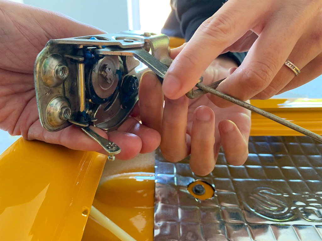
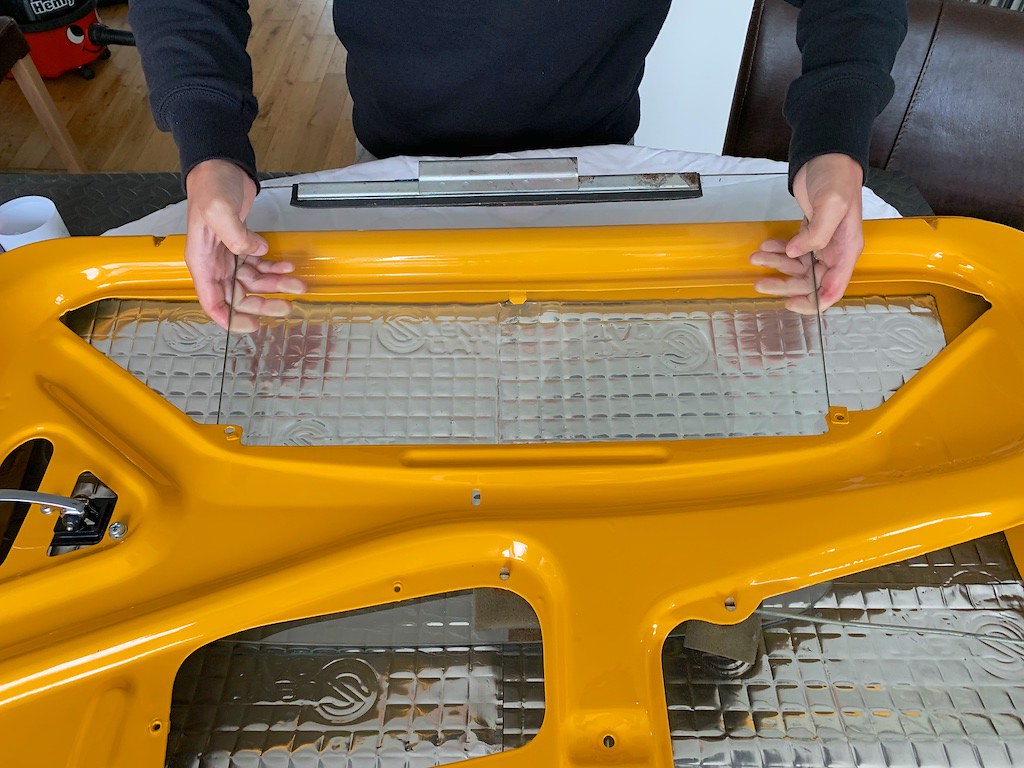
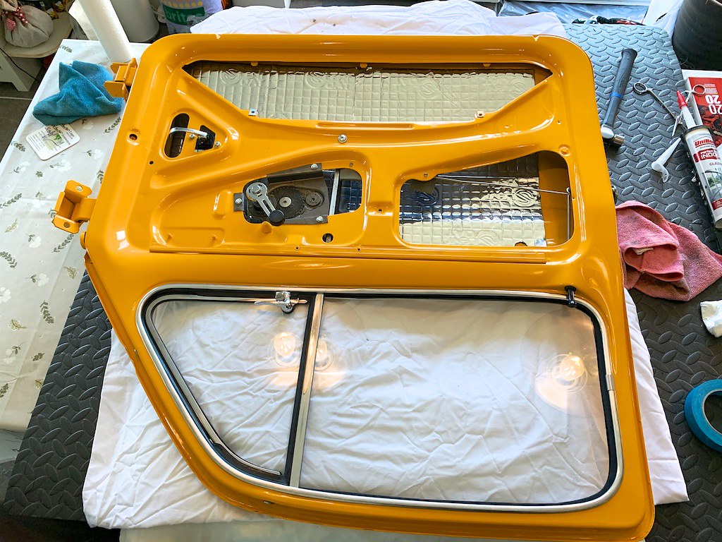
The quarterlights...this is the fun part. It helps to have two people here, or 3 hands, as you need to fit the glass and guide it into the channel on the quarterlight whilst simultaneously feeding the quarterlight itself into the door.

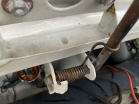
1st, make sure to grease the runner on the window guide for the regulator, then, insert the glass into the bottom of the door, feeding it around the metal stop bracket.

50308273268_d4d878e367_b.jpg


50308949001_5693eb9fdf_b.jpg


Be careful here, the inside edges of the door are sharp and can scratch the glass, we used a rag to protect the glass. The space you have is restricted by the support for the quarterlight.

50308273328_1e5755a362_b.jpg


Once the glass is in, use some beer mats to open up the slot between the front and rear skins of the door, you need to get it wide enough to get the guide on the quarterlight into the frame.

50316809538_3154664321_b.jpg


50308949146_eaa21ca850_b.jpg


Shown here is the orientation you need to have both the quarterlight and window glass in to get the to drop into the door. The top of the quarterlight needs to be fed in over the inside edge of the door frame as marked in the picture and lowered in parallel to the window guide, you can use some tape to protect the paint. Once in this position they should slide in together with plenty of room, and the glass should then be free to move again once it’s no longer being impinged upon by the quarterlight.

50309113837_72591a8568_b.jpg


At this point you can remove the beer mats and things should slide in freely

50309113792_aba55afd4b_b.jpg


Step 16.

Now fit the lock side guide, this has to be passed over the latch mechanism but you can rotate the glass out of the way.

50309113362_afebe66c7e_b.jpg


Step 17.

Fit the window regulator by threading it down below the glass, it’s a tight fit. Press the conical part into the guide on the glass by holding the sprung mechanism open and sliding it into the channel so it’s captive. You might need to use the winder handle to move the regulator to a more convenient angle.


Step 18.

Now with the glass pushed over and into the lock side guide and essentially where it will be once all the guides are in place, you can fit the middle guide. There is a small tab on the end that pushes into a receptor on the bottom of the runner on the quarterlight. It’s a little fiddly to thread this piece into the door, it’s getting pretty crowded by this point.

50308273683_d1760eccc7_b.jpg


Step 19.

If you didn’t fit the winder handle to move the regulator, fit it now. Make sure the window is wound all the way down, and measure then cut your door frame channel seal to fit, making sure it goes down into the door on the welded in part of the guide channel.


Step 20.

Apply a thin bead of adhesive to the window channel with a caulking gun, I used silicone window sealant. It only holds the seal in so you don’t need to go crazy with Sikaflex or similar. Once you have a thin bead, insert the seal making sure it’s pressed home all the way around the door, you can gently tap it with a mallet if needed. Then wind the window up all the way and leave it to set overnight.

50317709217_89e7ccff60_b.jpg


Job done!

I hope that’s a useful guide, if anything is not clear, please let me know.
 
Is anyone able to post a pic of how the spring fits for the bonnet stay please?
I can’t figure out how to attach it so that it holds the catch.

Thanks!
 
Today was a great day!

The bonnet now fits with nice gaps after the guys from the bodyshop popped round and tweaked it to fit and last week we also managed to get the passenger door to fit by modifying the catch. The gaps are all nice and even now. A thread update will follow soon.

With all that done we managed to get out for a test drive. The brakes are pretty poor and the pedal travel is long so we will address this tomorrow but other than that she runs a treat!

Does anyone have any tips for the brakes? We have tried forward and reverse with sharp brake application and they’ve been bled well. The brakes are all new and came as a full rebuild kit. We suspect it’s the springs as has been mentioned in other threads previously, but is there anything else we can look at?
 
Silly as it may sound Katie, make sure that the hand-brake is adjusted---3 clicks on the handle is optimum. The lining on some of the 'pattern' shoes is slightly thinner than the factory original (which is why Middle Barton have had a batch made for them by Ferodo to original specs) and, as you are aware, the 'pattern' return springs are often shorter than the original which makes them pull the shoes to far back on the 'self-adjusters'. They need to be pulled out to the same length as the original springs. Lastly, what size wheel cylinders have you fitted? Fiat did change the specification over time---the 'D' had 3/4" (19mm) wheel cylinders at both front and rear---I don't know if they were to the same specs on the 'L' model.
I am sure that you and 'im indoors know the correct proceedure for brake bleeding, but at the risk of "teaching you to suck eggs" start with the furthest at the rear from the master cylinder (on a RHD car that would be the NSR) and work your way progressively round so that you finish at the nearest to the master-cylinder (on a RHD car, that would be OSF).
 
..if you are certain they've been bled properly (a challenge in itself) then they should get better through use. I've been bleeding my brakes today and they are appalling compared to what they were before I replaced a brake-pipe.

They were bled in the sequence described elsewhere, furthest away 1st etc until no air remained. We will bleed for a second time this morning to see if it helps.
The main concern is the pedal travel. It doesn’t really engage the brakes until 80% travel.
They felt a little better after driving around the estate for a few circuits but still not good enough I don’t think.
 
Silly as it may sound Katie, make sure that the hand-brake is adjusted---3 clicks on the handle is optimum. The lining on some of the 'pattern' shoes is slightly thinner than the factory original (which is why Middle Barton have had a batch made for them by Ferodo to original specs) and, as you are aware, the 'pattern' return springs are often shorter than the original which makes them pull the shoes to far back on the 'self-adjusters'. They need to be pulled out to the same length as the original springs. Lastly, what size wheel cylinders have you fitted? Fiat did change the specification over time---the 'D' had 3/4" (19mm) wheel cylinders at both front and rear---I don't know if they were to the same specs on the 'L' model.
I am sure that you and 'im indoors know the correct proceedure for brake bleeding, but at the risk of "teaching you to suck eggs" start with the furthest at the rear from the master cylinder (on a RHD car that would be the NSR) and work your way progressively round so that you finish at the nearest to the master-cylinder (on a RHD car, that would be OSF).

The handbrake is adjusted well and the brakes were bled in that sequence but for a LHD, however, we’ll bleed again today to make sure.

The slave cylinders are 22.2mm front and 19.05mm rear according to the rebuild kit.

If bleeding doesn’t work then we will look at the springs next.

Thanks :)
 
Update on the brakes, we reset the handbrake according to the 3-click method, then bled the brakes in a slightly unusual way, but it worked.

We put the handbrake on as hard as we could to take the rear brakes out of the equation and using a hose clamp, clamped off one of the front brakes. This we assumed, would mean that upon pressing the brake pedal, all the fluid would be forced to one slave cylinder. We managed to get a small amount of air out of both fronts using this method, we got no air out the back.

The brakes are now much more positive, and we no longer have a long pedal, it’s very firm at about 50% travel. The brakes are still a bit pants, but as suggested, they prob need to bed in.
The car is running great with no issues, so its off for a geo ASAP and then we will get to enjoying the last of the summer weather here in the UK.
 
Update on the brakes, we reset the handbrake according to the 3-click method, then bled the brakes in a slightly unusual way, but it worked.

We put the handbrake on as hard as we could to take the rear brakes out of the equation and using a hose clamp, clamped off one of the front brakes.
The car is running great with no issues, so its off for a geo ASAP and then we will get to enjoying the last of the summer weather here in the UK.

The handbrake being on when bleeding is a bit of a red-herring. It does mean that the linings are in contact with the drums before you start and stops the shoes being pulled back if the springs are a bit too tight. But it does nothing to help clear any air from the respective brake pipes.

You were on the right track by clamping a front brake hose but in my case I eventually got fluid into the reluctant brake pipes by clamping all three of the hoses on the wheels I wasn't working on. This meant that there was theoretically a direct draw of fluid and bubbles only on the route to the wheel cylinder I was bleeding. It was a bit tedious continually moving the clamps around, but it worked. I was using a suction bleeder so your process might be affected differently in this technique.

Good luck with the "geo????? and I'm looking forward to seeing pictures of your little satsuma on the move photographed in the same high quality as those of the rebuild. :)
 
The handbrake being on when bleeding is a bit of a red-herring. It does mean that the linings are in contact with the drums before you start and stops the shoes being pulled back if the springs are a bit too tight. But it does nothing to help clear any air from the respective brake pipes.

The idea behind the handbrake being on was not to help expel air but to restrict the available system volume for the brake fluid thereby increasing the amount of fluid volume going to the remaining available brake, allowing the shoes to move further and stretch the springs.
The rears were bled without the handbrake on after the fronts had been bled.

Good luck with the "geo????? and I'm looking forward to seeing pictures of your little satsuma on the move photographed in the same high quality as those of the rebuild. :)

Wheel alignment :) Whilst we have adjusted it the best we can in the garage at home, from previous experience with other cars, it's best to get this done with the correct equipment.
 
Back
Top