General Weber 26/28 IMB

Currently reading:
General Weber 26/28 IMB

Joined
Aug 3, 2009
Messages
1,501
Points
365
Location
Sunshine Coast, Australia
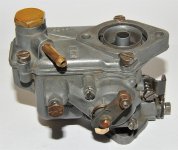
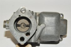
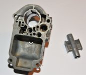
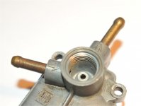
The little Weber IMBs are a very common, factory fitted, carburetor on the two cylinder, air-cooled Fiat engines. Yet despite this, there is a paucity of information available. Over my time of ownership I have collected a little bit of information about these carbies and intend to share what I have in the next few posts as well as some photos that I took recently of a carby stripdown.

The IMBs came in two varieties - the 26IMB fitted to the 500cc engines and the 28IMB fitted to the 650cc engines.

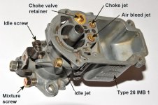
They also came in different states of tune, as indicated by the final number in the description. The 26IMB1 was fitted to the standard sedans whilst the 26IMB3 was fitted to the 'sports' engines. The 126 cars got the 28IMB3 up to November 1974 and the 28IMB1 or 28IMB10 thereafter.

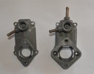
They are differ in minor details only and are virtually interchangeable.

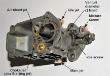
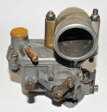
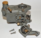
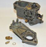
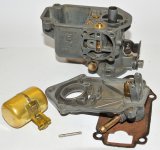
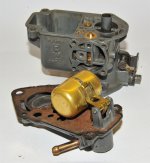
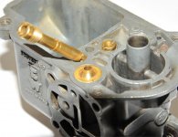
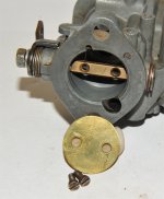
The carby is a simple downdraft single throat unit equipped with a starting (choke) device. The 26IMB has a 26mm throat diameter fitted with a non-removable 21mm primary venturi whereas the 28IMB has a 28mm throat with a 23mm primary venturi.

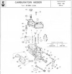
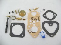
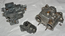
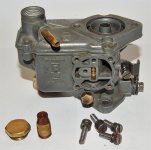
I have attached the section on the carburetor from the factory workshop manual (pdf). Also attached is a schematic diagram (jpg) and parts list (pdf) for the 28IMB and a picture of the major rebuild kit (jpg). Finally in this post is a comparative photo showing the size differences between the IMB and it's big brothers - the venerable DCD and the mighty DCOE.

Chris
 

Attachments

  • IMB Schematic.jpg
    IMB Schematic.jpg
    159.1 KB · Views: 2,996
  • IMB Major Rebuild Kit.jpg
    IMB Major Rebuild Kit.jpg
    141 KB · Views: 1,012
  • IMB DCD DCOE Comparison.jpg
    IMB DCD DCOE Comparison.jpg
    401.2 KB · Views: 894
  • Weber 26IMB.pdf
    4.6 MB · Views: 1,232
  • WEBER 28 IMB Parts.pdf
    33.5 KB · Views: 929
Following on from above are a couple of labelled photos showing the main removable components on a 26IMB. The carby cover has been removed.

The 28IMB differs in that the mixture screw is recessed and the main jet is screwed into the bottom of the fuel bowl rather than mounted externally. The choke valve retainer is also designed differently.

Throttle and choke controls are the same on both.

The 28IMB also has an excess fuel return pipe (connected back to the fuel tank) on the carby cover as seen on the right in the photo.

Chris
 

Attachments

  • IMB Labelled Parts 1.jpg
    IMB Labelled Parts 1.jpg
    343.2 KB · Views: 1,077
  • IMB Labelled Parts 2.jpg
    IMB Labelled Parts 2.jpg
    400.7 KB · Views: 1,029
  • IMB Covers.jpg
    IMB Covers.jpg
    385.4 KB · Views: 807
Carburetor Stripdown

A series of photos follow showing a stripdown of the 26IMB.

The first two show the front and rear of the carby with the air intake elbow attached. This is metal on the 500s and plastic on the 126s. It is also larger on the 126s.

The next two show the starting device and its removal (two screws)

The final photo shows the four cover retaining screws and the fuel inspection plug (19mm) and filter.

Chris
 

Attachments

  • IMB 1.jpg
    IMB 1.jpg
    656.2 KB · Views: 337
  • IMB 2.jpg
    IMB 2.jpg
    743.2 KB · Views: 370
  • IMB 3.jpg
    IMB 3.jpg
    577.6 KB · Views: 334
  • IMB 4.jpg
    IMB 4.jpg
    583.2 KB · Views: 353
  • IMB 5.jpg
    IMB 5.jpg
    667.5 KB · Views: 503
Removal of cover

Next the cover and float are removed as a unit.

The float fulcrum pin is a pinch fit between the two parts of the split post. Carefully drive it out from the split post end first using a suitable small punch. If you break off either of the ends of the split post, you will need a whole new cover, so please be careful.

Remove the float and check to see if it is in good condition. Gently shake it to hear if there is anything sloshing around inside - new ones are available cheaply if it is damaged or leaking. You can try to solder repair it, but you need to be good at soldering so as you don't heat the brass float too much. If you do, you drive the air out through the hole you are trying to repair and then when you have a seal, the float cools and collapses on itself under atmospheric pressure :eek:

Once the float is removed the old gasket can also be removed.

Next tip out the needle valve and unscrew the needle valve base (10mm) noting that there is an alloy spacer beneath.

Chris
 

Attachments

  • IMB 8.jpg
    IMB 8.jpg
    591.6 KB · Views: 300
  • IMB 7.jpg
    IMB 7.jpg
    613.2 KB · Views: 298
  • IMB 6.jpg
    IMB 6.jpg
    667.1 KB · Views: 312
Stripdown continued

Next remove the idle jet, mixture screw and main jet (10mm).

Clean the jets with a suitable solvent and blow dry with compressed air. Note the stampings on the side of each of the jets. These are the distal orifice diameters in millimeters and dictate the state of tune of the carby.

Inspect the end of the needle valve. You get a new one with the rebuild kit but if the old one has been screwed in very tightly, both the tapered end of the valve and the seat in the carby body may be damaged, though this would be unusual.

You also get a new idle jet o-ring seal in the kit.

Chris
 

Attachments

  • IMB 9.jpg
    IMB 9.jpg
    722.8 KB · Views: 330
  • IMB 10.jpg
    IMB 10.jpg
    630.4 KB · Views: 306
  • IMB 12.jpg
    IMB 12.jpg
    604.1 KB · Views: 872
Back to the top

Returning to the top of the carby, you can now remove the air bleed jet and its associated emulsion well beneath, the choke jet and the choke valve.

The choke valve is held in place by a split locking ring. Gently lever it up being careful not to lose either the ventilated guide or the spring. Hopefully the choke valve can now by easily removed. If it is stuck, replace the valve actuating mechanism on the outside of the carby, lubricate everything and work it slowly until it comes free.

The emulsion well can also be difficult to remove and if so, gentle tapping might dislodge it or if that fails, a short segment of soft wire can be used to hook it out.

Once again, clean all of these parts.

The last photo shows the carby body stripped of tunable parts.

Chris
 

Attachments

  • IMB 15.jpg
    IMB 15.jpg
    375.8 KB · Views: 262
  • IMB 14.jpg
    IMB 14.jpg
    713 KB · Views: 267
  • IMB 13.jpg
    IMB 13.jpg
    636.9 KB · Views: 259
  • IMB 11.jpg
    IMB 11.jpg
    477.1 KB · Views: 267
Butterfly and spindle

This part is optional but well worth doing especially if you suspect the spindle seals of leaking.

Remove the two screws holding the butterfly valve in place, rotate the spindle and draw out the valve noting which why it goes back in. It should be labelled with the number of degrees of chamfer around the edge - usually 78.

Be careful doing this lest you twist and deform the spindle.

Grip the spindle firmly but gently and remove the nut holding the throttle screw lever, its spring and washers. You can now remove the spindle so you can replace the two end seals if required. These are in the major rebuild kit as well.

Chris
 

Attachments

  • IMB 16.jpg
    IMB 16.jpg
    808.3 KB · Views: 216
  • IMB 18.jpg
    IMB 18.jpg
    641.7 KB · Views: 263
  • IMB 19.jpg
    IMB 19.jpg
    648.8 KB · Views: 235
Auxilary venturi

Now that you've come this far, gently tap out the auxilary venturi from below.

When refitting, match the orifices and note that it only goes in one way, so please don't force it. When everything is clean it will slip in very easily.

You now have a naked carby body ready for soda blasting or soaking.

I hope this quick overview has helped. Whilst the IMBs are very simple carbies they are, like all Weber products, well thought out and very well made. Having said that though, I replaced mine with a more sophisticated Dell'Orto unit. :D

Chris
 

Attachments

  • IMB 21.jpg
    IMB 21.jpg
    406.6 KB · Views: 197
  • IMB 22.jpg
    IMB 22.jpg
    535.3 KB · Views: 200
and finally ...

Forgot to mention at the outset the obvious stuff -

Disconnect the battery.

Disconnect and plug the fuel line.

Remove the inlet airbox connections.

Remove the throttle lever rod from the carby.

Remove the choke cable.

Remove the carby.

Disassemble, clean everything, replace worn parts, calibrate the float, reassemble and replace on manifold with new gaskets, reattach everything, start, adjust and go for a drive :)

Chris
 
Great work and an excellent reference source (y)

Does anybody know if the fuel return on the 28IMB can simply be plugged if fitted to a 500 with no tank return pipe?
 
Great info and pictures Chris, good idea to show the differences as the 28imb seems to be used a lot as a "performance' carb on the smaller engine. Would you think of doing a youtube video of the carb stripdown? Never know what it could lead to…TV…film…stardom!!

Colm.
 
I'll try to answer both questions.

Yes, the fuel return can be safely plugged. As you can see in the attached photo, the fuel return orifice is very small - nearly ornamental. Make sure the float is set correctly, use a good fuel pump and all will be well.

As to a youtube video - I'm just mastering the daguerreotype and you want me to make one of those new fangled moving pictures. With a bit of practice it could be done, though be warned, my friends and loved ones continually remind me that I have a good face for radio and then, of course, there is my colonial accent ... :D

Happy motoring,
Chris

PS: As you can see from the photos, I like Weber carbies. They are high quality pieces of engineering.
The main reason I changed my IMB was because it had only a relatively small fuel bowl that seemed prone to the effects of vibration and transmitted engine heat (despite the bakelite insulator) and it didn't have an accelerator pump. The carby that I'm now using (Dell'Orto FZD) has a deeper fuel bowl and a nice accelerator pump. It also allows reliable hot starting.
 

Attachments

  • Fuel return.jpg
    Fuel return.jpg
    274.7 KB · Views: 185
Last edited:
Think you're being modest Chris, you look like a cute little fella in your avatar!
And there is nothing wrong with a regional accent…we all have them!

Colm.
 
Well done Chris, a first class explanation of the 26/28IMB---I would make 2 observation however.
(1)--when removing the choke-valve, make sure that it is covered, the spring is strong enough to send the circlip, the spring cover and the spring itself into close orbit---I am still looking for my spring cover!
(2)---I have a 126 engine in my 500 (with a 28IMB on it) and have put a 'T' piece in the fuel line, in the engine bay, and connected the fuel return pipe from the carburettor to the 'T' piece. This way, any surplus fuel is 'cycled', which also helps to keep the fuel cool. Make sure that the return fuel pipe is protected from chafe as it runs behind the engines cooling-air pipe--I used a couple of lengths of old coolant hose, located and held in place with 'P' clips.
thumb.gif
 
Thanks for taking the time to do this Chris...

On some parts suppliers' sites (e.g., Axel Gerstl), there's numerous gasket sets for the 26/28IMB. I'm assuming that model number is written right on the carb: 28IMB3, 28IMB4, 28IMB12 so as to purchase the right set? Anyone know what the /250 after the number represents?

Generally with Weber the first number is the throat diameter so a 40DCOE is a double barrel carburetor each with a diameter of 40mm, a 28/32DCD is a progressive double barrel carburetor with a 28mm primary and a 32mm secondary and so on.

Occasionally the letters mean something as well eg: DCO = doppio corpo orizontale, literally, double body horizontal. The 'E' is the method of construction. I've no idea what IMB means ... ? cheap & cheerful maybe :)

The last number is specific to the engine that the carburetor was designed to fit. It describes things like where the progression holes are drilled, whether the butterflies are drilled, the angle of closure of the butterflies, the jets and emulsion tubes used etc.

Usually the renewable components (gaskets, seals, mixture screws etc.) are common within a series, eg: 45DCOE, 28IMB etc. Each of the kits on the various websites that I looked at vary depending on whether they are a major rebuild kit or just a service kit. Normally you'll only need a service kit and that should be the same for all varieties of 26IMBs and 28IMBs.

In short, I don't know specifically how a 28IMB250 is different to a 28IMB3 - there is so little information available - but a 28IMB service kit will fit all 28IMBs as will a 26IMB kit fit all 26IMBs.

Somewhere in amongst the shelves I have a 26 OC - the Giardiniera carby. If I find it, I'll clean it up and post some photos for those lucky guys with the wagons.

Chris

PS: Some years ago I had the privilege of touring the old Weber factory in Bologna. It was converted to a modern office suite for Magneti-Marelli years ago but there is a fascinating basement museum area devoted to all things Weber. The two guys who escorted me were retired Engineers who worked for Weber in the final days of its carburetor production in Italy. They told some great stories, showed me many old photos and of course, lots and lots of carbies :)
At the end of the day long tour one of them gave me a lift back to my hotel in central Bologna in his Fiat Punto - I think he thought he was Nuvolari ...
I corresponded with him up until he passed away in 2012. Lovely guy with a real passion for all things mechanical.
 
Hi, thank you for all of the useful information on this thread. I have followed the advice and refurbished my 28IMB Carb on my 650 engine in my Fiat 500. I have also replaced the fuel pump for good measure. I have two problems I would value your advice on:
1. The carb is over fuelling, i.e. starts from cold but quickly is flooded. I have checked the float and all of the settings and cannot find fault. One of the thread replies references the fuel return pipe. I have blanked mine off, however I would value your opinion on attaching this to a T in the fuel line before the fuel pump. Is this advisable, does this cause other problems.
2. Buying a replacement, they vary in price significantly. I am not looking to necessarily get the cheapest, I would like something reliable as I use the car for my daily commute! On a 650 engine what is the best carb to buy for reliability in your opinion.
Thanks
 
Wow! What a great write up. Thank you for taking the time to do this. I just wish I had it when I took my carb apart to change all the gaskets/seals :)
 
1. The carb is over fuelling, i.e. starts from cold but quickly is flooded.
2. Buying a replacement
Thanks

Hi tunk,

If the fuel pump is correct for the car and functioning properly, it will stop supplying fuel to the carby when the needle valve closes. I would suspect a dud float (? leaking and filling with fuel), an incorrectly set float, something jamming the needle valve open or possibly a missing aluminium needle valve spacer. Any of these will cause the fuel bowl to overfill. In isolation, blanking the return line should not cause the problems that you describe. There is something else going on.

As to a replacement carby, there is nothing fundamentally wrong with the IMBs, though because of their simplicity, they are a compromise. Personally I like the FZDs but they are horribly expensive. An SU can be made to fit, are cheaper and more available than the FZD and would be a better carby than the IMB. Ultimately, unless you are going to do some significant work to increase engine power, I'd persist with the IMB.

Chris
 
Back
Top