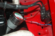
When I reinstalled the original engine, I left it wired up with the rebuilt generator. After completing the 695cc upgrade, I rebuilt the alternator (new bearings, brushes and voltage regulator) and wired it in when I installed the engine.
The alternator has a slightly different engine mount and also different cowling mounting so it would be tricky to install one on a standard 500cc engine without modification. As my 695 was based on a 650cc engine, I could use the cowling and mounts without modification.
From a general perspective, a generator (or dynamo) produces a DC current that increases with the frequency of rotation of the armature. Voltage regulation occurs when a relay switches the electromagnet in the stator on and off. They are simple devices but have the disadvantage of a relatively limited power output (due to heat generation) and a zero charge rate at low revolutions. On the other hand an alternator produces AC current from very low revs. The voltage is rectified to produce a DC signal and as before, the regulator varies the current to the stator in order to vary the output voltage. The advantage of the solid state regulators is that they have a range of regulation and are not on/off devices like the relays. Alternators therefore charge at low revs and are usually high capacity devices so you can run more electrical gizmos in your car.
The electrical conversion was not difficult.
In my car, the standard generator setup had a thick brown wire from the starter and battery connected to post #30 on the regulator where it picked up a red wire from the starter switch & fusebox. The thinner brown wire connected to the +ve on the generator ran back to post #51 on the regulator where a green wire from the warning light was also connected. The final connection was a black wire from post #67 on the regulator to the generator casing and earth.
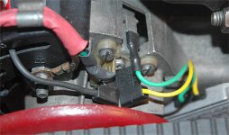
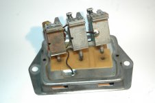
As I wanted to keep the look of the engine bay, I stripped the interior of the regulator and used what remained as 3 separate binding posts.
The alternator has a brown wire from the B+ terminal going back to join the red 12V line from the battery, starter motor and starter switch. these all connect together on the centre binding post. The green wire from the warning light was connected directly to the voltage regulator. The alternator and regulator were grounded through the case using the engine crankcase and strap to the chassis.
Between an idle of 800rpm to about 4000rpm, the output to the battery varies between 13.8V to 14.2V, which is just about right.
I've attached a few photos.
Regards,
Chris