

Basically, Fiat Uno lambda sensor produces a variable voltage in the range 0 - 1 V (in some cars there is another type of Lambda which produces 0 - 5 V voltage).
When mixture is correct, tension is about 0.5V, if it is lower, it means a poor mixture, if it is higher, it means rich mixture.
ECU reads this signal and corrects the fuel injection for correct carburation.
In order to check this voltage you can use a voltmeter.
But... this voltage moves from 0 to 1 (and reverse) 2 or 3 times every second. From the other side, a normal digital tester (a DVM) has a display time refresh more longer (for example 1 second). The consequence is that you photograph your lambda on every second and this is not very useful. Y'd need to photograph its excursion, and this means that you' d need a time refresh approx of 0.1 seconds (so you can appreciate voltages excursions during their develop).
I present an electronical stuff which permits to photograph this tension continuatively.
It is basically based on LM 3914 chip.
This chip contains all you need. You have to connect it only to some leds (which will light one after other as soon as lambda voltage will grow up), and two resistors. Then you also have to provide it with the 12 V of the car.
On national.com website you can download the datasheet for this chip, go to this www address and push on "download" for the pdf data sheet:
http://www.national.com/pf/LM/LM3914.html
I developed the circuit present on the second page of the pdf.
That layout permits to see 0 led lightning if input tension is 0V;
Provides 10 led lightning if input tension is 5V.
But Uno lambda develops only 0.8 or 0.9 V at top, so you have to put another resistor in circuit: if you watch to the formula in the datasheet, you 'll understand that the correct value is R2=0 ohms. Basically, you don't put any resistor in R2, you will only put R1 with the value of the sheet.
Then you have a voltmeter that lights on all leds with 1.25 input voltage (a little more of your max lambda voltage).
Then you connect the input pin of the chip with the output of lambda.
What you have to see on led?
When engine is cold you have to see some led ON (the first 2 or 3), because lambda is cold (no active output) and ECU goes in open loop.
As soon as it warms up, lambda starts to launch signals and ECU starts to correct injection up and down.
Then you have to see leds to light and stop from 0 led on to 7-8 led on, at minimum 1 time every second.
Where you can find lambda voltage?
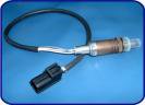
You have to see on your outlet mainfold: quite near engine head you will clearly see your lambda sensor (a metal cylinder with a cable which exits from it) put inside the mainfold and screwed inside.
You have to "follow" (not sure of this word) the cable (i mean watch the cable and analyze its run inside the engine compartment). It will go in the compartment, and on the left side (if you are in front of the car) you will see that this cable has a connector, connected with another cable.
(This connector is useful if there is the need to change lambda: you unscrew it and disconnect old lambda).
There is 1 connector or more probably 2 dependently by your car.
If there are 2 connectors, identify the brown cable (the 2 white are for warming up lambda and you are not interested in them), uncover it (there is an easy rubber big cover at the terminal which permits to cover/uncover it without any damage) and there connect the pin of IC.
The ground connection is provided by the chassis of the car (so you MUST connect IC power V+ pin to the +12V of the car, and connect the GROUND POINT of your IC to the chassis of the car. I used the "cigarettes fire" inside the car).
The better way is to provide a long cable from lambda connection to the inside of your car, where you will place your circuit.
Then try to go on road: when you push gas, you have to see leds light and not light alternatively.
If you relase accelerator, with engine more than approx 2000 rpm, you have to see all leds OFF: infact ECU cuts completely injection if you relase accelerator at warmed up.
If you can't develop the circuit,
you can use a normal digital tester.
Put the voltage scale to 2 V, put the black terminal to the ground (battery "-" pin), and put the red cable to the labda voltage pin.
Then you have to read a constant value at cold (approx 0.4 0.5V) and you have to see fluctuate that value when warmed up. But it's not as precise as the other circuit!
Let me know if it's not clear!
I'm not familiar with English.
Cheers!
Andrea.
When mixture is correct, tension is about 0.5V, if it is lower, it means a poor mixture, if it is higher, it means rich mixture.
ECU reads this signal and corrects the fuel injection for correct carburation.
In order to check this voltage you can use a voltmeter.
But... this voltage moves from 0 to 1 (and reverse) 2 or 3 times every second. From the other side, a normal digital tester (a DVM) has a display time refresh more longer (for example 1 second). The consequence is that you photograph your lambda on every second and this is not very useful. Y'd need to photograph its excursion, and this means that you' d need a time refresh approx of 0.1 seconds (so you can appreciate voltages excursions during their develop).
I present an electronical stuff which permits to photograph this tension continuatively.
It is basically based on LM 3914 chip.
This chip contains all you need. You have to connect it only to some leds (which will light one after other as soon as lambda voltage will grow up), and two resistors. Then you also have to provide it with the 12 V of the car.
On national.com website you can download the datasheet for this chip, go to this www address and push on "download" for the pdf data sheet:
http://www.national.com/pf/LM/LM3914.html
I developed the circuit present on the second page of the pdf.
That layout permits to see 0 led lightning if input tension is 0V;
Provides 10 led lightning if input tension is 5V.
But Uno lambda develops only 0.8 or 0.9 V at top, so you have to put another resistor in circuit: if you watch to the formula in the datasheet, you 'll understand that the correct value is R2=0 ohms. Basically, you don't put any resistor in R2, you will only put R1 with the value of the sheet.
Then you have a voltmeter that lights on all leds with 1.25 input voltage (a little more of your max lambda voltage).
Then you connect the input pin of the chip with the output of lambda.
What you have to see on led?
When engine is cold you have to see some led ON (the first 2 or 3), because lambda is cold (no active output) and ECU goes in open loop.
As soon as it warms up, lambda starts to launch signals and ECU starts to correct injection up and down.
Then you have to see leds to light and stop from 0 led on to 7-8 led on, at minimum 1 time every second.
Where you can find lambda voltage?
You have to see on your outlet mainfold: quite near engine head you will clearly see your lambda sensor (a metal cylinder with a cable which exits from it) put inside the mainfold and screwed inside.
You have to "follow" (not sure of this word) the cable (i mean watch the cable and analyze its run inside the engine compartment). It will go in the compartment, and on the left side (if you are in front of the car) you will see that this cable has a connector, connected with another cable.
(This connector is useful if there is the need to change lambda: you unscrew it and disconnect old lambda).
There is 1 connector or more probably 2 dependently by your car.
If there are 2 connectors, identify the brown cable (the 2 white are for warming up lambda and you are not interested in them), uncover it (there is an easy rubber big cover at the terminal which permits to cover/uncover it without any damage) and there connect the pin of IC.
The ground connection is provided by the chassis of the car (so you MUST connect IC power V+ pin to the +12V of the car, and connect the GROUND POINT of your IC to the chassis of the car. I used the "cigarettes fire" inside the car).
The better way is to provide a long cable from lambda connection to the inside of your car, where you will place your circuit.
Then try to go on road: when you push gas, you have to see leds light and not light alternatively.
If you relase accelerator, with engine more than approx 2000 rpm, you have to see all leds OFF: infact ECU cuts completely injection if you relase accelerator at warmed up.
If you can't develop the circuit,
you can use a normal digital tester.
Put the voltage scale to 2 V, put the black terminal to the ground (battery "-" pin), and put the red cable to the labda voltage pin.
Then you have to read a constant value at cold (approx 0.4 0.5V) and you have to see fluctuate that value when warmed up. But it's not as precise as the other circuit!
Let me know if it's not clear!
I'm not familiar with English.
Cheers!
Andrea.
