General Wiring spaghettii

Currently reading:
General Wiring spaghettii

timgarman

Established member
Joined
Oct 8, 2012
Messages
712
Points
254
Location
Wanganui, New Zealand
Hi Folks

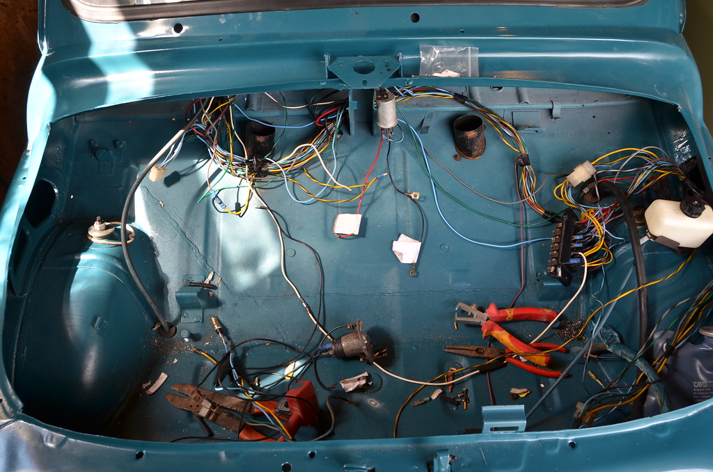
I'm just at the stage of laying out the wiring loom from my 500F, in fact, we have some of it in the car now. It was removed some 3 years ago and carefully labelled. Most of these have now fallen off or the notes have become unreadable... I'm hoping this is a familiar story... or it may just be sheer stupidity. :bang:

Can anyone upload, or direct me to some photos that show some of the significant wiring points. For example, under the bonnet coming from the fusebox. I also need to know which hole under the bonnet these pass through, there are a couple of possibilities.

Also, wires extruding from the empty tail light holes would be helpful.

I do have wiring diagrams, but we are talking 50 year old wiring, with central locking and an alarm added (both now removed) plus 50 years of grime and tinkering. It also doesn't help that my genius mechanical friend is sadly colour blind. :(

Thanks in advance for any help anyone can give.

Tim
 
I found the wiring diagram s in the Haynes manuals once enlarged were extremely easy to follow when installing my new loom
Fuse box and column switches even seemed straightforward
Do you have such a book or would you like a scanned copy?
 
I've got photos and wiring diagrams Tim. Will post tomorrow. If I forget PM me
Damian
 
Tim, I've got pictures of my F front loom with switches etc connected. Some are covered in looming tape but you can see the colours and they are pretty hi def when viewed on a big screen.

I don't know if this helps?

Tony


Oh and watch out for the four pole wiper switch - wrong terminals gives a dead short
 
How much did BA sponsor your restoration Tony?

Our national airline has quite a few shares in mine so far! Haha.

Chris
 
I don't want to over-load your thread with unnecessary photos Tim so if you want any in particular give me a shout. I have plenty so I'm sure I can help you out however it will only be of use if you have the same loom. I have bought a new loom for mine (F series 1) so I am going to have to rely on circuit diagrams when it comes to fitment. I have attached two versions of these I have.View attachment Schema elettrico 500 F 1 serie.pdf

View attachment F electrics v2.doc
 
How much did BA sponsor your restoration Tony?

Our national airline has quite a few shares in mine so far! Haha.

Chris

Hi Chris are you referring to my lacing and looming?? A little trick that I picked up years ago courtesy of the RAF and I was surprised I could still remember how to do it.:idea:
 
I found the wiring diagram s in the Haynes manuals once enlarged were extremely easy to follow when installing my new loom
Fuse box and column switches even seemed straightforward
Do you have such a book or would you like a scanned copy?

Hi Andrew

I've got the Haynes, thanks for the offer. In fact, since it's in black and white, it's actually very helpful for my colour blind mechanic. :)

Tim
 
Hi folks

Awesome response as ever.

Tony, those pics will be very helpful thanks.

Damian – don't know if it's the same loom but mine is a 500-F, 1966. It's the original wiring, as far as I can tell and we are planning to re-use.

Best if I shout for some specific photos if we get stuck.

Tim
 
I have an original (Fiat factory) work-shop manual (as well as an original parts manual), so if anybody ever wants a copy of the wiring diagrams, or parts pictures/original parts numbers just let me know and I will happily put a copy into the post.
thumb.gif
smile.gif
 
I realize this is a 7 yo thread but instead of starting a new one I thought I'd try here first. Other that the battery and the engine where are the other electrical grounds located? I have a good battery and everything runs fine. All of the lights are acting like I have a ground issue.
Thanks
Bill
 
There aren't really many other 'grounds' in the way a modern car would have the wiring run from each component to collected ground locations. Most components just ground through their mounting points to the body shell.

If I remember correctly, the rear lights ground through the upper mounting screw for the light unit, the front indicators and side repeaters ground through their mounting bolts. The headlights themselves I think have a proper ground wire that runs back into the loom.

That kind of grounding through the mountings can easily be disrupted by corrosion, or by a fresh coat of paint on the body shell!

I presume a previous owner had this issue with my car as the rear light units had a wire soldered on to the copper track for earth inside the light unit, with then ran to a spot inside the engine bay where it could be screwed to the body shell to make an earth.

I went one step further and created grounding studs at each corner of the car, more like a modern car would have. I figured a nice stud with good bond to the shell and a nut to hold the wires on would be more reliable long term than the self tapper approach the previous owner used! I then made wires with ring terminals on each end, to run from my new earth studs to the mounting bolts of each light component.
Very helpful!
Thank you
Bill
P.S. I hate automotive wiring!
 
Back
Top