Technical Cooling fans do not start Fiat Ducato 230 -00 2.8idtd

Currently reading:
Technical Cooling fans do not start Fiat Ducato 230 -00 2.8idtd

KentSture

New member
Joined
Feb 9, 2021
Messages
6
Points
1
Hello,

The cooling fans on our motorhome do not start, the temperature rises.
The car is a fiat ducato 230 -00 with the 2.8IdTd engine.

I have tested most things, i need some tips, below is what I have done so far.


supply the fans directly with 12V and they both start.

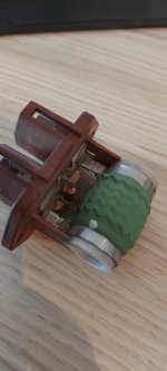
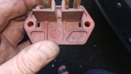
hot wired the cabel to the sensor in the bottom of the radiator and both fans start, one pin 1 fan and the other pin both fans.

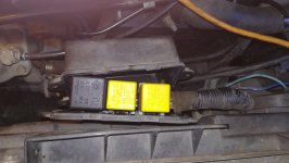
taken out the relays and tested these, they close when supplied with 12V and conduct current without problems

let the car idle, the thermostat opens and circulates as it should (almost new)

Replaced the sensor with a new one in the hope that it would be the one, but no difference. The temperature gauge in the cabin was above normal temperature and then one fan should start as I understood it.

checked all fuses ocularly they are whole

Anyone have any further tips on what I can check?

Thanks in advance!
 
There is likely a ballast resitor thing somewhere nearby. Often a cylinder 15mm diam and may be 80 to 100mm long these buggers are regular fan stoppers on many cars. They are usually near the rad or fixed on the chassis somewhere nearby. I would be bet money on it being your issue. Trace back down your fan supply lines and hopefully you may find it.
 
There is likely a ballast resitor thing somewhere nearby. Often a cylinder 15mm diam and may be 80 to 100mm long these buggers are regular fan stoppers on many cars. They are usually near the rad or fixed on the chassis somewhere nearby. I would be bet money on it being your issue. Trace back down your fan supply lines and hopefully you may find it.
Thanks for the reply, i will go and have a look.
 
Many years ago I had a 1990 Talbot Express, which was equivalent to a Series 1 Ducato.
The fans were controlled by a twin contact thermostat (sensor). The thermostat had 3 connecting wires namely, earth, contact 1, and contact 2, which operated at a higher temperature.

Only two output wires are mentioned in the initial post, so is the earth connection made via the thermostat body? This would not work well with rubber radiator mountings, and hoses.

Is it possible that an incorrect replacement part has been fitted previously, and inadvertently replaced with a matching part? Any signs of alterations to the wiring?

Perhaps I have got it wrong, but I would not expect grounding one wire to operate both fans? All other checks mentioned appear to give the correct result.
The connector has 3 wires/pins, so when i "hot wired" it i stuck a piece of wire betwen earth (-) and the contact 1 and later contact 2.
And the result is just as you decribe, on contact activates one fan and the other contact both of the fans.

Im quite sure i got the right parts on order, but i could double check that.

All the wiring is looking factory, no work seem to have been done there.
 
Hi,

I am still puzzled as to why earthing contact 1 operates one fan, and earthing contact 2 operates both fans.

What would be the reason for this, since if the engine temperature continued to rise after Fan 1 was operated, the second contact would eventually close and operate Fan 2. The observed operation of two fans from one contact could be achieved by using a blocking diode between the two relay coils, but I do not think that this is likely.

When hot wiring, were you using the earth wire in the thermostat cable, or a separate earth connection?
I used a separate wire that i stuck betwen the diffrent contacts in the pin, so in that sense i used the earth in the thermostat cable.
 
There is likely a ballast resitor thing somewhere nearby. Often a cylinder 15mm diam and may be 80 to 100mm long these buggers are regular fan stoppers on many cars. They are usually near the rad or fixed on the chassis somewhere nearby. I would be bet money on it being your issue. Trace back down your fan supply lines and hopefully you may find it.
I gather this is the bugger you where refering too :)

It is rated 23K Ohm, and i get almost nil out of it when measuring.
It was placed in the upper part of the radiator.

Gonna put one on order now and replace later, will come back to you with the results.
 

Attachments

  • processed-591756f3-c7bb-482d-b2b9-a17c3e312668_xj0PGztl.jpeg
    processed-591756f3-c7bb-482d-b2b9-a17c3e312668_xj0PGztl.jpeg
    451.9 KB · Views: 82
Hi

The resistance of these parts is very low, so 0.23 ohms (Nought Point Two Three Ohms or 230 milliohms) is more likely. An ordinary ohmmeter will read near zero if it's OK. If it's failed it will read infinity / open circuit.

Guessing at 15 Amps for the fan current, a 0.23 ohm resistor will drop 3.5 volts, which will leave about 8.5 volts for the fan

These things dissipate 50 watts and are designed to run hot, which accelerates any tarnish/corrosion on the electrical contacts, so check these (and the mating half) are clean and bright.
 
Last edited:
I had reached a similar conclusion to @Anthony489, but as I see it the resistor(s) would be in circuit when Kent hot wired the sensor connector. The fans operated, so surely the resistors are proven intact?
 
Hi

The resistance of these parts is very low, so 0.23 ohms (Nought Point Two Three Ohms or 230 milliohms) is more likely. An ordinary ohmmeter will read near zero if it's OK. If it's failed it will read infinity / open circuit.

Guessing at 15 Amps for the fan current, a 0.23 ohm resistor will drop 3.5 volts, which will leave about 8.5 volts for the fan

These things dissipate 50 watts and are designed to run hot, which accelerates any tarnish/corrosion on the electrical contacts, so check these (and the mating half) are clean and bright.
It was marked 23K on the body of the spool so i though 23 K Ohm, just checked and i get about 0,5 ohms.

Connectors look ok, not that much tarnish, nearly none.
 
Just a thought, what temp was the gauge showing, often the fan won't kick in until about 3/4 of the way up the gauge obviously not to the red but well higher than the middle, or have you heard it working before at similar temps to now showing? Some vehicles bring the secondary fan on to cope when aircon on.
 
Also a thought or question from me. You have stated that earthing one wire operated one fan, while earthing the other wire operated both fans. If this observation was based on sound level, then could it have been both fans at reduced speed, and then both fans at full speed?

As an aid to diagnosis, I have spent some time trying to find a circuit diagram. Having downloaded from this forum a workshop manual linked to by @ben, I was unable to find a relevant diagram. Another search led me to an eLearn diagram for an x244 with aircon which uses a ballast resistor. OK its for an x244, and a JTD engine with ECU, but if you delete the ECU, and substitute a sensor with contacts for that with thermistors, than you have a diagram to build from. Of course wiring colours may differ. The diagram shows a third relay J028. On the x244 relays with the "J" prefix are mounted under the plastic windscreen wiper cover in the engine bay.

However, as everything seems to check out OK, may I commend the suggestion made by @bugsymike, and my bit about sound levels.
 

Attachments

  • eLearn E5020 Engine Cooling Fan Aircon.pdf
    111.3 KB · Views: 82
As Communicator says.
Also have you got a way of testing the coolant temp independently, such as a laser temp tester, if aimed at the radiator it could also show if the bottom tubes of a radiator were partially blocked resulting in a cool spot were the fan switch is located causing it not to kick in.
Years ago I had an LDV 200 van that always ran at normal on the temp gauge suddenly leapt to three quarters under load and even after stayed at that temp. The cause was the rubber sealing gasket inside the plastic radiator had become dislodged so instead of directing the water through the whole radiator cooling tubes merely sent it through the one hose and out the other!
 
I have been looking at the operation of the fans on my x230 recently, below is what I've gathered so far. As Anthony489 points out, the ballast resistor is a very low resistance, see photo, 0.23ohms. I have been through the same loop as Communicator looking for a circuit diagram. It is missing from the German language manual. As Communicator points out, you can surmise that the thermoswitch on these vans is in place of the ECU connection on the x244 eLearn circuit diagram.

My van has Aircon, it has 3 relays located inside a box next to the resistor on the back of the radiator, see photo. The thermoswitch comes as two different part numbers, the changeover date is on the EPER diagram, I don't have it in front of me but I can get it if you want. The two part numbers have slightly differing temperature ranges, something like 82-87-92, and 87-92-97, again I'm working from memory. The temperature ranges give the on/off characteristics of the two switches inside the thermoswitch, i.e. switch #1 87 off/92 on, switch #2 92 off/97 on, for example. Each switch has 5⁰ hysteresis.

I believe the operation to be as follows (Aircon van): upto 92⁰ no fan, 92-97⁰ fan#1 running at low speed through ballast resistor, above 97⁰ fan#1 at full speed plus fan#2.

Hope this helps with your diagnosis. As has been said before, it depends on the temperature of the coolant at the switch as to whether the fans cut in as they should. Your tests sound like the system is doing what it should, electrically.

Regards
 

Attachments

  • IMG_20220701_184211.jpg
    IMG_20220701_184211.jpg
    1.9 MB · Views: 52
  • IMG_20220701_191612.jpg
    IMG_20220701_191612.jpg
    2.4 MB · Views: 83
I should add, you have to factor in the hysteresis when looking at the operation, e.g. as the temperature falls, fan#1 will cut out at 87⁰. The hysteresis gives the system a 'memory' of what has gone before.
 
Hi

I looked at the eLearn diagram posted by Communicator and it looks to me like there is an error by Fiat (not unusual), as it shows both fans wired in parallel which makes no sense. I have re-drawn the diagram as my "Best Guess" at how things work - see attached photo. I don't guarantee that this is correct, it's just a guide to the way Fiat do things ! (Slight error, Fan 2 is N012 not N011)

Below 87 degrees C (say), both temperature sensor contacts are open circuit and no fans run.
Between 87 and 92 degrees C, one temperature sensor contact is closed which earths the coil of the blue relay. The relay closes and allows Fan 1 to run at reduced speed (15 Amps draw) via the ballast resistor.
Above 92 degrees C, both temperature sensor contacts are closed. This causes the green relay to bring in Fan 2 (25 Amps draw), and the red relay shorts out the resistor allowing Fan1 to increase to full speed (20 Amps draw).

From the tests by Kentstur of bridging the temperature sensor with wire, it would appear that all the electrical side of things is working OK. If the temperature sensor is also OK, it suggests that there is a physical cause preventing it from seeing the true coolant temperature. Maybe it would be a good idea to remove the sensor and use a hose to blow air into the orifice and /or gently poke a rod into the hole in case there is a build up of sludge in this area ?
 

Attachments

  • Fiat Engine Fan - Best Guess.jpg
    Fiat Engine Fan - Best Guess.jpg
    39.9 KB · Views: 90
My compliments to Anthony on detecting the error, and producing a more readable layout of the diagram.

May I point out that the applicability of the original drawing to an x244 is suspect. My eLearn CD for the x244 shows a single element temperature sensor. The diagram was obtained from the 4cardata website via a web search, but using a more general route to the 4cardata site, eventually leads to a diagram identical to that on my CD
 
I have been through the same loop as Communicator looking for a circuit diagram. It is missing from the German language manual. As Communicator points out, you can surmise that the thermoswitch on these vans is in place of the ECU connection on the x244 eLearn circuit diagram.
I attach the diagram to which I referred. I assumed there would be only one version, obviously not.
 

Attachments

  • IMG_20220721_184843.jpg
    IMG_20220721_184843.jpg
    2 MB · Views: 88
I attach the diagram to which I referred. I assumed there would be only one version, obviously not.
I confirm that the diagram posted by Womo793 matches that on my eLearn CD. I was trying to warn that the other version which was previously posted by me, may have limited validity.
 
Back
Top