over the last week my cam vairator has failed and now sound like a diesel so going to got to fiat tomorrow and buy a new one (115 pound) but also been told it can be the solenoid is this true is so how can i check it working? anyone got part numbers for them both? thanks kieron
Here's a section from my "never finished" variator guide...

Solenoid Test
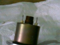
This is the place to start if you're questioning the operation of your variator. The variator solenoid is located in between the fuel injectors on the top of the engine and the solenoid body is made up of two parts, the first being the main metal body and the second being the plastic cap. This cap provides the connections to allow the plug to attach to the main body of the solenoid. The picture below shows the contact pins of the main body of the solenoid which protrude from the body, into the cap where they poke into some solder. this solder provides the connection between the plug and the main body of the solenoid... and it's not exactly reliable to say the least. In case you don't know what the variator solenoid is, basically it's an electromagnetically activated piston which works on the principle that passing a current through a coil of wire creates a magnetic field within it. The iron piston located in the middle of the coil gets moved by the magnetic field against a spring allowing oil to fill the variator, thus activating it. When the current stops, the spring forces the piston back to its original position, allowing the oil pressure to drop in the variator, returning it to its normal position.
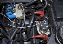
What you need to do to test the solenoid solder connection is very simple, just put a multimeter across the two solder blobs located on top of the solenoid cap (shown below in a pic from an Alfa but the the variator is exactly the same). The multimeter needs to be in "continuity test" mode (then one that beeps when you touch the probes together) and the idea is to put each probe to one of the solder blobs on the top of the cap. The mulitmeter should beep continuously, if not, then the contacts have dried out in the cap meaning that the solenoid may not be actuating when it's supposed to as the coil can't generate a strong enough magnetic field to move the piston.
If you're not getting the continuous beep then you need to take the cap off the solenoid to repair the solder connection. To do this, remove the solenoid plug and unscrew the two philips screws on the top of the cap. Now DO NOT twist the cap to take it off as the pins of the main body will get damaged. To remove the cap you can gently prise it off working around the cap in 90 degree increments to lever it off little by little. Once you've got the cap off, you can look into the holes where the pins of the main body would go into the cap. At the bottom of the holes, you'll see the bottom of the solder that you saw on the top. There will be indentations in the solder where the pins make contact and what we want to do is to put a single drop of solder down into each of the holes to create a nice new fresh contact.
Once you've dropped the solder into each of the holes, you can put the cap back on and screw it back down. Now don't screw it down too tight as you don't want to risk damaging the pins with the added solder. When the cap is back on, you can retest the continuity again with the multimeter... with a bit of luck, you'll get a nice continuous beep.
Solenoid Activation and Variator Functionality Test:
This is another simple test carried out with the engine running to see if the solenoid and variator are functional. The solenoid has a permanent 12v on one of the pins it but the other pin is only grounded by the ECU when the variator is to be actuated. This means that you can test the solenoid by grounding one of the terminals (the bottom terminal I think, test this yourself by using the multimeter and testing the voltage between the chassis and each solder blob on the top of the solenoid cap. Whichever doesn't give you a voltage reading, is the one you want to ground). So... with the engine running, briefly touch a wire between the chassis and the solder on the cap that is supposed to be grounded by the ECU.
If everything is working as it should in the solenoid and the variator then the engine should almost stall straight away. This is because the variator has altered the inlet valve timing at idle meaning that the inlet valve is open at the wrong time messing with the compression and ignition. This is good news as they're both functioning! The next test is to see if the the ECU is grounding the solenoid contact when it's meant to.