Technical ABS DTC C1107 No instrument panel communication

Currently reading:
Technical ABS DTC C1107 No instrument panel communication

Joined
Nov 17, 2016
Messages
16
Points
2
I have the classic "Brke.lamp fail" message along with the "yellow warning triangle" at start up

I have tried most of the solutions on this forum (e.g new brake light bulbs, contact cleaning, connectors, checked the fuse's, replaced the brake switch etc):confused:

Thought about replacing the crystal in the instrument panel, but came across the fault code on interrogating the ABS - "C1107" with the explanation/info "No instrument panel communication"

(naturally I tried clearing the code - but it remains)

So I'm now Looking for some help to diagnose the issue /possible solutions - before I loose all my hair:eek:
 
Also Read the CAN status, on the Body Computer - an extract being ......

"CAN UNIT WITH GENERIC ERRORS
Engine control (NCM)
Brake system node (NFR)

CAN UNIT WITH CURRENT ERRORS
Brake system node (NFR)"
 
Well I changed the 8M Hz crystal oscillator as per the solution given by other threads - but the problem still remains "brkr.lamp fail" with the yellow triangle at startup :(

I hope that someone elsecan offer some advice........ :confused:
 
Hi "The Fox":
Ref "Does the fault go after start up.?" After starting

-The yellow triangle stays on all the time
-The "Brke.lamp fail" message disappears

(When starting, I think that the yellow triangle appears first and then the message!)

Or do you mean the fault code C1107?
 
As it's a communication error, I assume you've already checked the CAN wiring continuity and connections between the various connected components? i.e. Instrument Cluster, ABS ECU, Body Computer, Engine Management ECU?
.
 
Hi Davren:

ABS CAN continuity – wanted to, but not directly as I’m not sure which pins are the CAN lines? (1.9 JTD) – see below my logic so far:

-Body computer & Instrument cluster, over the “OBD” connection works fine, this functions (I believe) over the CAN, thus I “assumed” CAN continuity is OK

-Over the body computer I “Read the CAN Status” where - Instrument Cluster, ABS ECU, Body Computer, Engine Management ECU, were “visible” so again assumed that the CAN continuity was OK!

-The “gray area” for me being the ABS CAN lines……. REF “CAN UNIT WITH CURRENT ERRORS
Brake system node (NFR)"

-So I have visually checked and cleaned the ABS connector & pins (connector M50 I think) - next to the ABS unit - thinking that if it is a continuity problem then it would be from the ABS to the Body computer?

-To really make sure that the continuity is OK I would appreciate some help to determine the exact pin-out on the connector/s and thus where to check


Side Notes:
1) My understanding is that the ABS provides the “status” to the body computer over the C-CAN – the Body computer then processes this further to the Instrument panel over the B-CAN

2) I read on an Italian site about fault code C1107 with the same symptoms - it was not possible to really understand, but I think that the conclusion was that the instrument panel was at fault rather than the ABS CAN, which surprised me! but persuaded me to change the 8M Hz crystal
 
To really make sure that the continuity is OK I would appreciate some help to determine the exact pin-out on the connector/s and thus where to check

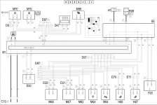
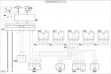
This is the CAN wiring diagram.

Looks like the CAN wires from the ABS ECU (M50) go via the D4 connector to the Engine Management ECU (M10), then to the Electric Steering ECU (M86), then to the Body Computer (M1), then to the Instrument Panel (E50).
.
 

Attachments

  • CAN Wiring (1).JPG
    CAN Wiring (1).JPG
    143.1 KB · Views: 298
  • CAN Wiring (2).JPG
    CAN Wiring (2).JPG
    112.1 KB · Views: 247
From what I remember this is a software issue with the instrument cluster. Low battery voltage or a weak battery also seemed to cause it.
It's been a while since I worked on a stilo with that fault, can't remember if we replaced the cluster or updated the software.
 
Hi Davren & TheFox:

Thanks for the guidance - very much appreciated.....

I think my objective is to naturally try to fix this if I CAN;)

thus determine
-If it is a wiring/connection fault etc
or
- Instrument cluster needing a "costly" repair!

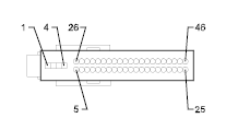
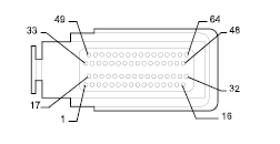
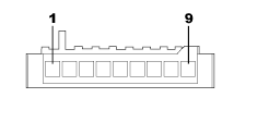
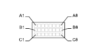
I have mapped out the pin connections:

Unit CAN L (pin) CAN H (pin)
ABS*ECU*(M50) 40 24
D4 connector C4 C5
Engine Management*ECU*(M10) 28 29
Engine Management*ECU*(M10) 9 10
D4 connector A3 A4
Electric Steering*ECU*(M86) 7 8
Electric Steering*ECU*(M86) 5 6
Body Computer (M1) 36 37

CAN A (pin) CAN B (pin)
Body Computer (M1) 6 5
Instrument Panel (E50) 4 3


Side notr Info
 
Woops....sorry... lets try that again....

Can you please help with the pin-out and location of:
-M1 Body Computer?
&
-M86 Electric Steering?

Plus help to confirm that the diagrams I have found for the others and attached, are correct?

Again your help and time is very much appreciated(y)

My mapping- as per your sequence Davren....

Unit CAN L (pin) CAN H (pin)
ABS*ECU*(M50) 40 24
D4 connector C4 C5
Engine Management*ECU*(M10) 28 29
Engine Management*ECU*(M10) 9 10
D4 connector A3 A4
Electric Steering*ECU*(M86) 7 8
Electric Steering*ECU*(M86) 5 6
Body Computer (M1) 36 37

CAN A (pin) CAN B (pin)
Body Computer (M1) 6 5
Instrument Panel (E50) 4 3


Side Note/Info:
Instrument panel is
3FCF - 10849 - JB
SW Ver 38A,
HW Ver: CA
F3JB075365

31/01/04

shown M10/D4/E50/M50
 

Attachments

  • M50.png
    M50.png
    4.3 KB · Views: 610
  • M10.png
    M10.png
    6.7 KB · Views: 61
  • E50.png
    E50.png
    2 KB · Views: 594
  • D4.png
    D4.png
    3 KB · Views: 598
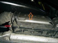
... the connector M10 I'm not sure how to remove it!

I assumed to pull the slide in the direction of the red arrow then lift up in the direction of the orange arrow?

I don't want to use too much force until I'm sure!
 

Attachments

  • M10 con.jpg
    M10 con.jpg
    67.7 KB · Views: 79
Can you please help with the pin-out and location of:
-M1 Body Computer?
&
-M86 Electric Steering?

Body Computer (M1) is the grey box attached to the back of the dashboard fuse box.

Electric Steering ECU (M86) is attached to the ES motor on the steering column.

... the connector M10 I'm not sure how to remove it!

I assumed to pull the slide in the direction of the red arrow then lift up in the direction of the orange arrow?

I don't want to use too much force until I'm sure!

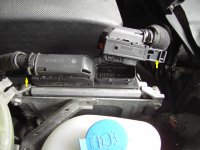
Yes.... pull the locking engagement slide in the direction shown by your red arrow. There's an angled slot in the slide, so that as you pull the slide, the connector should lift by itself.

The wiring bundle going into the connector can obstruct the slide from coming out. Lift the wiring bundle before pulling the slide. You may need to gently lever the slide with a screwdriver to get it started. I found it easier to get the rear connector off, if I disconnected the front one first.
.
 

Attachments

  • ECU Connectors.JPG
    ECU Connectors.JPG
    525.9 KB · Views: 84
Last edited:
Thanks for the clarifications....( & the picture helps a lot)

I'm still not sure about M1!

is it the connector on the left (see arrow) or is it behind this panel?
 

Attachments

  • M1 con.gif
    M1 con.gif
    251.7 KB · Views: 81
I'm still not sure about M1!

is it the connector on the left (see arrow) or is it behind this panel?

No... That's one of the fuse box connectors.

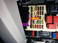
The BC connectors are the black and blue connectors with red locking clips at the bottom in your picture, and there's another blue with red locking clip at the back of the BC.
.
 

Attachments

  • Body Computer.jpg
    Body Computer.jpg
    282.2 KB · Views: 115
Last edited:
ahhhh..... I checked the wrong connector before then:eek: thanks for putting me in the right direction (again the "picture-is-worth-a-thousand-words" (y))

I presume I have to remove the "fuse panel/body computer" to get to the connector at the back?


I will FIRST check as suggested the CAN

Side Note/History: Body computer did have -
"Error code: U1602
CAN line error
Wiring faulty
Fault intermittent
Battery voltage: 12.00 V"
Which I cleared - "touch-wood" reading the Body computer DTC's reports "No Faults" now for a long time!


- but just to think "worse-case"!.......IF .... C1107 leads to ....

the instrument cluster is defective is it possible for a DIY'er to test them?, (or is the only way to swap it out with another one that's known to be working?)

I presume however this is not "simple" because a second hand instrument cluster would have to be re-programmed once installed in the car to get it functioning correctly - correct?

Sorry for all the questions, but just trying to give myself the best "Heads-Up"
 
I presume I have to remove the "fuse panel/body computer" to get to the connector at the back?"

Yes... unless you can get your hand to the back of it.

IF .... C1107 leads to the instrument cluster is defective is it possible for a DIY'er to test them?, (or is the only way to swap it out with another one that's known to be working?)

I don't know of any way to test the instrument cluster, other than by substitution.

I presume however this is not "simple" because a second hand instrument cluster would have to be re-programmed once installed in the car to get it functioning correctly - correct?

Providing you fitted a replacement with the same part number, it shouldn't need reprogramming. It would keep the mileage (kilometerage?) of the car it came from, but that can be adjusted upwards with MultiECUScan. MES will not adjust it downwards.

A different part number cluster (e.g. from a different model Stilo) would work, but may need the Proxy Alignment procedure carrying out, and depending on what model it was from, some of the functions will not work.

For example; I fitted a Stilo Abarth multi colour display cluster in one of my Stilo JTDs. The Abarth cluster has a colour display for oil pressure and oil temperature gauges, but because the JTD engine doesn't have those sensors, the cluster can't show those gauges. Also, the JTD engine has an oil level sensor, but the Abarth cluster doesn't have an oil level display. Also, the diesel clusters RPM dial only goes up to 6000 RPM, whereas the petrol ones goe up to 8000 RPM. The petrol one fitted to my JTD still shows the correct RPM though.
.
 
Earth Point locations

Hi: I would appreciate if someone has actual pictures of ALL the earth point locations on a Stilo JTD? - (I have searched this site without any luck :confused:) - The diagram from the manual is not so useful - I want to eliminate any potential earthing problems behind the "fault-codes" I'm reading - Thanks....
 
Well --- managed to get through winter (just), but now with warmer weather, its time to start the investigation again, more fault codes now B1029, B100E B100C :confused:
 
Back
Top