Off Topic Who's our resident Electronics guru?

Currently reading:
Off Topic Who's our resident Electronics guru?

Joined
Nov 30, 2006
Messages
2,780
Points
692
Location
Coventry
have a question about the LCD screens used on the abarth clocks (the ones to display time and mileage)

since removing them and changing the led from orange to white i have dead segments on each display... in my haste and frustration i have stupidly pulled 5 of the pins off the clock display but oh what little i do know about LCDs, arent they just friction connected anyway?

the mileage display survived unscathed but still has dead segments. my soldering is usually spot on and im 99% sure theres nothing wrong with my connections from leg to board.

i have 2 scenarios... ive either used too much heat and managed to burn the inserts from the board or the resistance is wrong in the circuit due to the different LEDs.
 
It looks as though they plug into sockets in the PCB and the white plastic clips hold them in. LCD displays are very delicate, so any excess heat near them could cause damage.
.
 

Attachments

  • PICT1701.JPG
    PICT1701.JPG
    840.7 KB · Views: 41
the white cages are exactly that they space the displays off the board to allow illumination from the LED behind. the legs go through the cages and solder onto the board. is it possible to test each segment? if so what sort of voltage do they run on?
 
Long time since I did anything with LCD displays, but I seem to remember they needed a driver/multiplexer IC to drive them.

It's probably possible to drive the segments individually, but you would need the correct current limiting resistors depending on the specifications of the LCD display.
.
 
feared as much... well that goosed it!!

theres no numbers on the displays so theyre not generic :( 
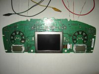
look like special ones by visteon... i dont fancy my chances trying to find spares for it :bang:
 
Did you use wick or a vacuum pump to desolder them? If you used wick, you may have got them too hot.

With wick, you have to get the component and the pad on the PCB and the wick hot before the solder flows. With a vacuum pump you only have to get the component and the PCB pad hot, so the component is hot for less time.
.
 
vacuum pump. heated untill it flowed, then, sucky sucky
i only use wick for cleaning up pads

as always i *try* to keep heat on components to a minimum fried soooo many LEDs when i was practising using too much heat

usually solder at about 180*C and desolder at 210-240. clean the tip every use (just habit) and use .5mm 60/40 fluxed wire
 
Last edited:
The length of the LCD pins means that it is unlikely that the LCD connections are heat damaged. If they are damaged, it is more likely to be mechanical stress.
It is more likely that excess heat has lifted the PCB pads, whilst de-soldering, and damaged the connection to the PCB tracks.

On my most recent product with an LCD, when I have had a damaged LCD which needs to be replaced I cut the LCD from the pins and desolder each pin individually. With plated-through holes in the PCB, it is difficult to remove all the solder from all the joints, so there is mechanical stress on the pins and the PCB pads when forcing the LCD off, as the remaining solder between the legs and pads shears.

The LEDs will be driven independently from the LCD. White LEDs have a higher forward voltage than orange LEDs, so switching to white may mean that the LEDs are dimmer (or off), but the LCD operation should not be affected by the LED colour. (The glass gap on the LCD should ideally be designed to match the wavelength of the illumination colour, but this would only affect the perceived colour and white is not a single wavelength so the gap can only be a compromise. This will not be the problem).

How many segments are there on each LCD ? On Davren’s photo, the left LCD appears to have 13 pins and the right hand LCD appears to have 18 pins. LCD drives are often multiplexed, which means that more segments can be driven with the same number of pins, e.g.
13 pins: 1:1 drive (or static drive) for up to 12 segments (12 segment pins x 1 common pin)
13 pins: 2:1 drive for up to 22 segments (11 segment pins x 2 common pins)
13 pins: 3:1 drive for up to 30 segments (10 segment pins x 3 common pins)
13 pins: 4:1 drive for up to 36 segments (9 segment pins x 4 common pins)
There may be fewer segments if one or more pins are just ground connections, for static discharge protection.

LCD segments must be driven with alternating polarity, so that the average voltage across the segment is 0V, otherwise the segment will degrade over time.

The multiplexing and the alternating drive make it difficult to test the LCD without the right equipment.

For this sort of product it is very likely that Visteon had custom displays, in which case you won’t be able to buy the LCDs on their own.
 
Back
Top