Technical Driving wheel connectos pinout

Currently reading:
Technical Driving wheel connectos pinout

RJose

New member
Joined
Apr 6, 2009
Messages
50
Points
11
Hi guys,

Can anyone point me where is pin 1 from connector C (behind the driving wheel) connected?
What is the function of this pin?
I can't find it anywhere on eLearn.
The connector B is mainly lights switch inputs. Connector A and most of pins on Connector C are for controlling the wipers and water spraying. I can't find it anywhere.

Thank you
 
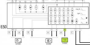
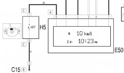
pin 1 of the 'C Connector' on the back of the stalk arrangement (H5) is connected to pin 8 of the 'A Connector' (black plug) of the instrument cluster (E50)

it is on eLEARN... ;)

H5Cpinout.jpg

E50A8.jpg

H5C1.jpg

it would seem it is the wiring for the 'Trip' button on the wiper stalk (y)

hope this helps
 
Last edited:
Wow, let me say, what a BOSS! Thank you very much, I suspected it was from the trip button but somehow I gave up on that by seeing some diagram I don't remember... but in the picture you posted is perfectly clear. Thank you. I'm on a project regarding the lights switch and an arduino, I'll be happy to share it when I'm done. Maybe someone want to implement it as well. Regards
 
Last edited:
please let this be light activated headlights... im soo interested in that... the kits are a little too expensive for my liking. i didnt think about the arduino route!

you could put the light sensor in the little blank in the middle of the dash (for those of us without alarms) between the screen vents ;) and a variable resistor to adjust light sensitivity... unless you're REALLY clever you could implement it into the CAN and control the light sensitivity via the dash but i think that would be a MASSIVE ask
 
Last edited:
In fact it is light dependent headlights:))) I'm doing it just for fun, but at this moment I have the software almost as I want it and and the soldering part just waiting for a diode to be added and it is completely done. It's a very simple project, the fun part is hacking the stilo and soldering stuff. The software is also very simple. I'm not hacking can communication, I will use the lights pins to acomplish switching, and a ldr(photoresistor) for light sensing. I was thinking in putting it where you said, but there is infrared sensor isn't it, under that dome? Another thing is that the all project is really unexpensive and very fun:))) I'll put some pictures later.
 
Last edited:
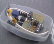
20131024_125458ff-455300203.jpg
I took it in low light with the tablet. I'll post some nice pics after everything done, and also the BOM, diagrams and the arduino script;)
 
Back
Top