Technical Selespeed Paddles linked to Cruise Control

Currently reading:
Technical Selespeed Paddles linked to Cruise Control

Joined
Mar 1, 2013
Messages
64
Points
15
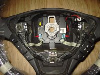
I've recently fitted all the toys from a fully loaded Abarth into my JTD, everything is working as is should and its great to have all the extras. I also fitted the 11 button steering wheel to operate the CN+

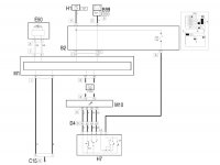
The Abarth was Selespeed and so the steering wheel also has + and - paddles for gear shift which are obviously now redundant in my JTD. I quite like the idea of linking the wiring of these paddles into the cruise control circuit and using the paddles + and - to operate the cruise control speed. Anyone got any thoughts as to whether this is possible, a good/bad idea and tips on the best way to do it? If anyone could point me in the direction of the wiring diagrams for these circuits that would be great. I still plan on keeping the standard cruise control stalk fully functional with the facility to turn cc on and off.
 
as far as i know the paddles are on microswitches and are effectively part of a 'control box' that communicates over the CAN. depending on how savvy you are you could replace the microswitches (probably only rated at 5v or under) for some beefier ones that can handle 12v @ 7.5amps... and rewire them somehow to bypass the CAN...

your biggest problem will be transfering the power from the switches to the loom of the car, as it will all be done with 'clockspring' type setups i would have thought, if the paddles move with the column.
 
Last edited:
as far as i know the paddles are on microswitches and are effectively part of a 'control box' that communicates over the CAN.

The paddles work by pushing a sprung loaded small piece of what looks like brass or something similar, onto a circuit board which then makes the circuit by bridging 2 contacts on the board. I dont know if this is classed as a microswitch or not?

your biggest problem will be transfering the power from the switches to the loom of the car, as it will all be done with 'clockspring' type setups i would have thought, if the paddles move with the column.

Im actually using the Abarth wiring loom behind the dash, so I have in place the wires coming from the clockspring down the steering column.
I was kind of thinking that it might be possible to cut into the paddle wires here (so effectively I have 2 wires for the + paddle, and when I press the paddle it completes a circuit) and series wiring the paddle switch into the cruise control switch circuit so whether I use the CC switch or paddle switch, either one completes a circuit and increases speed, then the same for the - paddle. Make sense?

Any idea where I can get circuit diagrams for selespeed paddle circuits and CC circuit?
 
Sounds like a novel idea. JTD 8v Cruise Control wiring is below.

The rotory up/down speed part of the CC switch (H7) sends a +ve signal to pins 57 or 56 respectively of the engine management ECU (M10). At that point, I suspect you could add extra switches. They would have to be wired in parallel, not series as you posted. If you wired them in series, all switches would have to be on to complete the circuit.

I've only had time to have a quick look at it, but it gets more difficult using the paddles as the extra switches. All the steering wheel buttons and paddles are multiplexed. The information regarding which button(s), and/or paddle is pressed is then sent via the CAN.
.
 

Attachments

  • JTD Cruise Control Wiring.JPG
    JTD Cruise Control Wiring.JPG
    62.8 KB · Views: 85
Sounds like a novel idea. JTD 8v Cruise Control wiring is below.
.

Thanks for that.

They would have to be wired in parallel, not series as you posted. If you wired them in series, all switches would have to be on to complete the circuit.
.

lol yeah I meant parallel - its been a long time since my schoolboy electronics days!

I've only had time to have a quick look at it, but it gets more difficult using the paddles as the extra switches. All the steering wheel buttons and paddles are multiplexed. The information regarding which button(s), and/or paddle is pressed is then sent via the CAN.
.

Ah I feared that might be the case, thats a shame. Ideally I'd like to rewire those paddle switches and loop it onto the CC circuit but still go through the clockspring. Im assuming its not really possible to put an extra couple of circuits through the clockspring though, and I cant really think of another way of doing it unless is possible to use the signal generated when the paddle is press, which would normally trigger the gear change, and feed that into the CC circuit somehow, but that idea seems a little unnerving to me!?
 
I've got a spare multiplexer, steering wheel buttons and clockspring to play with, but not the Abarth paddles.

The paddles plug into the two blue sockets arrowed red on the picture below. If you have the steering wheel with paddles, can you post how many wires there are on each, and which pins of the two sockets they plug into. Also, how many pins are there on the socket arrowed yellow in the picture, and how many wires plug into it.

Di you know if the symbols on the paddles are illuminated?
.
 

Attachments

  • Steering Wheel Center.JPG
    Steering Wheel Center.JPG
    715.8 KB · Views: 80
I've got a spare set too, the original one that I took off the car but it's only 6 button. I'll check the paddles wiring and let you know.

Isn't the yellow arrow on your diagram where the clockspring plugs into? Im using the original JTD clockspring from the 6 button steering wheel as I think the one from the Abarth may have been faulty/damaged (the steering wheel buttons didn't work when I bought it) All 11 buttons work fine through the JTD clockspring and yes the + and - symbols on the paddles also illuminate.

I kind of assumed the clocksprings were the same (prob same part number?) hence same wire and pin count but I'll check.
 
Back
Top