Technical OCS simulator photos

Currently reading:
Technical OCS simulator photos

Joined
Jan 7, 2012
Messages
194
Points
48
Location
Birmingham
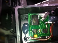
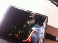
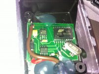
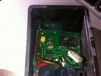
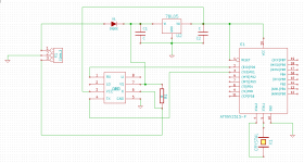
Right everyone, after having problems a long time with the airbag light, I decided to get the simulator. Haven't drawn a schematics of it but hope the photos will be enough. I can confirm that it does work and now I have no airbag failures :D happy days

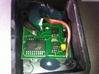
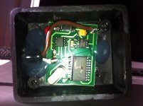
There are 2 resistors in there (I think they are resistors) with no writing and have no clue what Ohms they are.

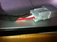
Here are the photos:
 

Attachments

  • ocs1.JPG
    ocs1.JPG
    1.5 MB · Views: 169
  • ocs2.JPG
    ocs2.JPG
    1.4 MB · Views: 110
  • ocs3.JPG
    ocs3.JPG
    1.4 MB · Views: 93
  • ocs4.JPG
    ocs4.JPG
    1.4 MB · Views: 82
  • ocs5.JPG
    ocs5.JPG
    1.8 MB · Views: 101
  • ocs7.JPG
    ocs7.JPG
    1.6 MB · Views: 67
  • ocs6.JPG
    ocs6.JPG
    1.5 MB · Views: 80
im in the process of transfering to a PCB Schematic but need a little more info.

ive found the data sheets for 2 of the ICs (the large one and the 8pin one closed to the red wire) the 8pin one closest to the brown wire is a voltage reg (78LO5A in chip form) and im assuming the one labelled M4.000D1D is a transistor but im not finding anything on google. the one stamped with SID or SJD could be a cap. but im not sure and ill need resistor values for those 2 pictured (cream coloured one below the voltage reg and the white one nearest the white wire)

what does the yellow component have written on it?

the problem were going to have is the large IC is an ATtiny 2313-20SU made by Atmel and its programmable... without knowing what info is stored within, its not a simple solder onto the board jobbie. we'll be needing someone to read/write the chips if were gonna be making them ourselves.

all this is just guess work at the moment ill get into looking at what pins are connected to the what and see if we need to program that chip or whether we can use it as-is
 
Last edited:
It surely does look one sided. Will pull it out soon and check all that is written.
And yes, I was afraid that it would need programming but if we do get someone who knows how to read the IC then we should be sorted. I will ask a friend who's good with electrical stuff and see if he has a programmer.
 
hence why i think the board is dual layered!;)(y)

edit:-
unless the track that goes under the IC is connected to Pin 20 seems a bit of an arse about tit way of connecting it but hey

edit2:-
heres my attempt so far.... some things confirming and some extra tracks putting in but its WIP. (im assuming pin 20 is getting a feed)
PCB2.jpg
 
Last edited:
Reading the code from atmel chip might prove difficult since they can be locked. The 2313 communicates with the OBD chip with serial interface, so you could snoop out the message and response with logic analyzer/scope.
Looked the pics a bit and one sided might be enough, since if it were dual layer, they could have placed the connecting wires in a single connector. Also the clear pads between pin 6 and 10 seems to be for bypass cap, and as its underneath the chip, I cant see where pin6 is connected on the 2313.
 

Attachments

  • em.png
    em.png
    13.9 KB · Views: 114
The "identical tab" things are the place to put another bypass cap (like under 78L05) to smooth the voltage, or maybe a resistor or some other SMD part. I suspect there runs a trace under the chip to pin 6 from somewhere (like there is trace between pin 1 (active low reset) and pin 20 (Vcc)). Otherwise I do not see any reason for the pin to have a trace running to/from it. Possibly it is tied to RX line to have it create interrupt and wake the micro from sleep?
Without the programming/schematic it is hard to guess.

Ive got all the info on the AT chip at home on my laptop pm me your email and ill fire it over (220page PDF)or you could take the time to search Google its upto you
 
Back
Top