hi my radiator fan does not cut in when the temp hits half way the temp gauge never goes above half no matter how long its being running.i disconnected the sender switch in the thermostat housing and as soon as i did this the fan kicked in i have elearn but the wiring diagrams are not on so a bit stuck at the moment so any help would be much appreciated


You are using an out of date browser. It may not display this or other websites correctly.
You should upgrade or use an alternative browser.
You should upgrade or use an alternative browser.
Technical radiator fan
- Thread starter ms24
- Start date
Currently reading:
Technical radiator fan
On many engines, the radiator fan doesn't need to switch on when driving during the winter with cold ambient temperatures.
The fan started when you disconnected the engine temperature sensor because the engine management ECU had detected the 'missing' sensor so switched the fan on permanently rather that risk the engine overheating.
Wiring diagrams are in eLEARN but are sometimes difficult to find. Having selected your engine size and year range, you need to navigate to Electrical Equipment > Electrical Functions > Engine Control and Management Systems > Engine Cooling > Engine Cooling Wiring Diagram.
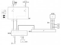
Below is the 2.4 engine cooling wiring diagram. B1 = Engine fuse box. K120 = Air conditioning linear pressure switch. M10 = Engine management ECU. M150 = Fan control ECU. N11 = Engine cooling fan. The engine temperature sensor will be shown on the Petrol Engine Electronic Management wiring diagram.
.
The fan started when you disconnected the engine temperature sensor because the engine management ECU had detected the 'missing' sensor so switched the fan on permanently rather that risk the engine overheating.
Wiring diagrams are in eLEARN but are sometimes difficult to find. Having selected your engine size and year range, you need to navigate to Electrical Equipment > Electrical Functions > Engine Control and Management Systems > Engine Cooling > Engine Cooling Wiring Diagram.
Below is the 2.4 engine cooling wiring diagram. B1 = Engine fuse box. K120 = Air conditioning linear pressure switch. M10 = Engine management ECU. M150 = Fan control ECU. N11 = Engine cooling fan. The engine temperature sensor will be shown on the Petrol Engine Electronic Management wiring diagram.
.
Attachments
hi my radiator fan does not cut in when the temp hits half way the temp gauge never goes above half no matter how long its being running.i disconnected the sender switch in the thermostat housing and as soon as i did this the fan kicked in i have elearn but the wiring diagrams are not on so a bit stuck at the moment so any help would be much appreciated
Are you quite sure the fan isn't coming on? I ask because I thought I had the same problem, no obvious sound of the fan kicking in, but like you, the temp needle never went above halfway.
In fact, I believe the fan has two stages/speeds and the initial stage is pretty quiet, particularly if you're trying to hear it over the noise of the 2.4 at idle. It's also not easy to see the fan itself, looking from above. In the end by putting my ear close to the air inlet in the lower bumper, I could hear the fan switching on.
You may have a fault of course, but worth trying...
hi cheers for your help so far i know for a fact the fan doesn't kick in no matter how long the cars being running, as for the wiring diagrams i can find where they are on elearn but the picture is blank dont know why,as for my problem i presume there is a sensor in the rad so at the weekend i plan to disconnect it and cross and bridge the connection and if it comes on this would mean the sensor is at fault.what would ye think of this idea
There is no sensor in the radiator, that's the way it was done years ago. On your car the engine temperature sensor gives out the info and the car's ECU and the rad fan speed ECU do all the work
Davren supplied wiring diagram for your car up above
If you have FES working then you can test select rad fan slow and fast speeds. If not then have a look in Stilo Guides how you can make very simply a variable resistor simulator of eng temp instead of your engine frying
2.4 engine has a rad fan speed control ECU M150 out front near the radiator and it's very common for this to have electrical problems as heat and dampness isn't good for electrics
Last edited:
as for the wiring diagrams i can find where they are on elearn but the picture is blank dont know why
You may need to install the SVG viewer to see the wiring diagrams, It should be on the eLEARN CD.
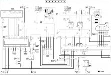
This is the wiring diagram for the engine ECU. K36 is the engine coolant temperature sensor situated on the thermostat housing.
.
Attachments
Last edited: